We Recommend:
Bach Steel - Experts at historic truss bridge restoration.
BridgeHunter.com Phase 1 is released to the public! - Visit Now
New Westminster Railway Bridge
Fraser River Swing Bridge
Primary Photographer(s): Nathan Holth
Bridge Documented: August 25, 2014
New Westminster and Surrey: Greater Vancouver District, British Columbia: United States
Metal 17 Panel Pin-Connected Baltimore Through Truss, Movable: Swing (Rim Bearing Center Pier) and Approach Spans: Metal 16 Panel Pin-Connected Baltimore Through Truss, Fixed
1903 By Builder/Contractor: Dominion Bridge Company of Montréal, Québec and Engineer/Design: Waddell and Hedrick of Kansas City, Missouri
1976
380.0 Feet (115.8 Meters)
1,780.0 Feet (542.5 Meters)
Not Available
1 Main Span(s) and 7 Approach Span(s)
Not Applicable

View Information About HSR Ratings
Bridge Documentation
View Historical Articles About This Bridge
About This Bridge
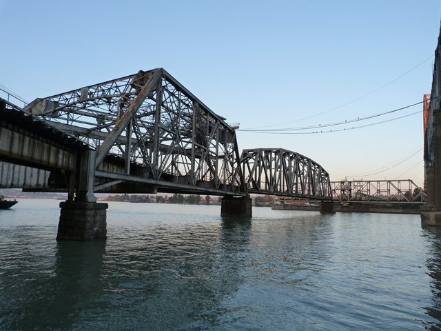
The only crossing of the Fraser River at this location when completed, the New Westminster Bridge was built as a double-deck bridge, serving railway traffic on the lower deck and vehicular/pedestrian traffic on the upper deck. Since the completion of the high level fixed Pattullo Bridge in 1937 provided a new crossing for vehicular traffic, the New Westminster Bridge has been known as the New Westminster Railway Bridge, referring to its exclusive use by railway today. The upper deck has been removed, with the major exception of the support bents and girders on the truss spans which remain in place. The upper deck ran through the middle of the three larger through truss spans at the west end of the bridge, and on the top of the five smaller truss spans at the east of the bridge. One of the bridge’s several fixed through truss spans was destroyed by a boat collision in the 1970s and was replaced. Otherwise, this historic bridge retains its original design and appearance.
The New Westminster Railway Bridge proper is considered from the western end to the eastern end of the eastern truss span. Excluded from the bridge proper are the extremely long three elevated railway structures that branch away from the east end of the bridge... these spans are composed of short timber spans. Excluding those timber spans, as well as the western approach spans west of the truss spans, the New Westminster Railway Bridge is 1,780 feet long. The bridge was completed in 1903 and includes a swing span. Designed by the firm Waddell and Hedrick, the bridge is one of the earliest surviving works of noted bridge engineer J. A. L. Waddell. The prolific Dominion Bridge Company was the superstructure contractor, while Armstrong, Morrison, and Balfour was the substructure contractor.
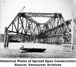
As described above, the bridge is unusual and historically significant due to its double deck design and association with Waddell. But there is a third item which makes this bridge one of the most unusual and noteworthy truss bridges in Canada. At the New Westminster end of the bridge, the railway was designed to split and curve off in two directions in a “Y” configuration, while the upper deck proceeded directly away from the bridge at elevation. To accommodate the “Y” of the railway, a unique span with one end being vastly wider than the other end was created. It was described in Engineering News and historical photos as a “spread span.” This through truss span has end posts spaced 19 feet apart from each other at the interior (east) end, matching the dimensions of the other bridge spans. The outer end of this span (west end) however, has end posts spaced 136 feet apart! This alone would make the span unusual and greatly contributes to its bizarre appearance. However the uncommon double-deck design also led to some unusual engineering. Typically, a double-deck bridge has the upper deck’s floor beams fastened directly to the trusses. This is the technique used on most of the New Westminster Railway Bridge. However, on the wider half of the spread span, the upper deck actually rests on steel bents which in turn rest on the floor beams of the lower deck. There are two reasons for this. First, since the lower deck’s railway tracks are curving away at this point there is room below for these bents to exist without obstructing the lower deck traffic. Second, the trusses are so far apart at this point it was likely not economical to attach them to the trusses in the traditional manner. During construction, the spread span was assembled a short distance away from its final position and then floated into position.
Most truss bridges enjoy symmetry both in engineering design and visual appearance. The spread span of this bridge does exactly the opposite. The unusual angles of the trusses combined with the upper deck’s varying methods of support all combine to create a truss that visually looks like a chaotic mess. Steel members can be seen leading off in nearly every direction imaginable on this bridge!
Photographic History of the Bridge: Construction, Grand Opening, and Fixed Span Collapse/Replacement
An unusual number of historical photos of this bridge were located online. For this reason, HistoricBridges.org is offering the photo-oriented narrative that describes the important chapters in the history of this bridge. Photos are grouped accordingly, and discussion appears below each photo group.
As with any bridge, construction began with the substructure. Above, the leftmost photo shows a caisson being sunk, and to the right, a stone pier under construction.
The above photo shows the smaller Pratt truss spans being erected. Two of the spans appear to be mostly complete, but with the falsework still in place. To the far right, an erection traveler which provided the function of today's cranes can be seen on top of the falsework as erection of that particular truss span is just beginning.
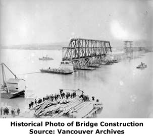
The large fixed Baltimore truss span was constructed off-site next to the smaller fixed truss spans and then floated into place. Above, the span is seen in its temporary assembly location.
Above, the large fixed Baltimore truss span is being floated into its final position.
Above, the large Baltimore truss span is in place, and falsework and traveler are in place to begin erection of the swing span to the right of the large Baltimore truss span in the above photo.
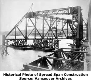
Much of the spread span was constructed alongside the smaller fixed through truss spans at the east end of the bridge. The eastern spans provided a location for workers to stabilize the truss by running cables from the eastern spans to the under-construction span, which can be seen in the above photos (click for enlargement). In the above photos one of the truss lines is assembled, but the other truss line has not been erected yet.
The above photo showing the off-site construction of the spread span next to the eastern spans of the bridge shows the spread span with both truss lines erected and the portal bracing being installed. The above two photos were taken from opposite ends of the spread span, and do a good job of contrasting the different widths of the truss ends.
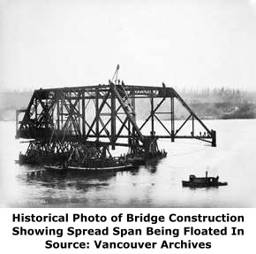
Once the trusses and overhead bracing of the spread span were assembled, the truss was floated into its place. Note that the flooring systems have yet to be installed. Here, the truss is still in the off-site location, but is ready to be floated away.
In the above photo, the spread span is being floated into position.
In the above photo, the spread span is being floated into position and has essentially arrived at the final position.
With the spread span in place, construction of the western approach spans commenced as seen here.
Workers loved to pose for photos showing them standing on the bridge they worked as seen in the above photo.
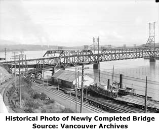
The completed bridge opened to substantial fanfare as seen in the above photos. The grand opening and dedication saw the bridge's upper deck packed with people, and a fair number exploring the lower deck as well. A banquet was also held.
The above photos show the completed bridge as originally built, with the upper deck in place and in use.
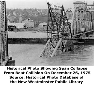
On December 26, 1975, disaster struck (literally) as an out of control log barge, called the Swiftsure Prince crashed into the bridge, the result of winds reaching 40 knots which blew the barge from its moorings sent it upriver where it collided with the large fixed Baltimore through truss span sending the entire span into the river, and irreversibly destroying the span. From a historical standpoint, the bridge was lucky, because the more historically significant spread span and swing span could easily have been hit instead but were spared.
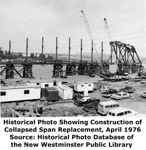
A new truss span was constructed to replace the destroyed span as seen in the above photo. By this time, the bridge had not served vehicular traffic on an upper deck for decades, and as such, the replacement span was not double-deck and was a traditional single deck truss span.
About Ira G. Hedrick
Regarding the designing firm of Waddell and Hedrick, the biography of J.A.L. Waddell, famous engineer and author of Bridge Engineering, is well documented, but the biography of Ira G. Hedrick who for a short time worked with Waddell is not as well known. The below biography was taken from the 1908 publication Kansas City, Missouri: Its History and Its People 1808-1908, Volume 2.
Ira G. Hedrick, a civil engineer, who is making a specialty of the building of bridges and viaducts, was born April 6, 1868, in West Salem, Edwards county, Illinois, his parents being Henderson and Mary Ann (Bryan) Hedrick.' The father, born in 1837, was a farmer by occupation, whose great grandfather Hedrick came from Holland and founded the family in New York in 1755. The mother was a daughter of Gideon Bryan, of Clay county, Illinois.
At the usual age Ira G. Hedrick became a pupil in the public schools of his native town and when he had completed the course there he continued his studies as a preparation for business life in the Arkansas State University, where he was graduated with the degree of Bachelor of Civil Engineering in 1892, while in 1901 the degree of Civil Engineer was conferred upon him. In 1898 he received the degree of Bachelor of Science and in 1899 that of Doctor of Science in McGill University, at Montreal, Canada, In October, 1892, he put his technical knowledge to the practical test by entering business as a civil engineer in connection with J. A. L. Waddell, at Kansas City, continuing as his assistant until 1898. when he became assistant to the chief engineer of the Kansas City, Pittsburg & Gulf Railway. A year later he formed a partnership with Dr. Waddell under the firm style of Waddell & Hedrick. They did a large amount of important bridge work, including the bridges over the Missouri river at St. Charles, Missouri; at Jefferson City, Missouri; and East Omaha, Nebraska: over the Miami river at Toledo, Ohio; the Red river at Index, Texas, and at Alexandria, Louisiana; over the Frazer river at New Westminster, British Columbia; over the Arkansas river and the White river in Arkansas, and all bridges on the Vera Cruz & Pacific Railroad, and many large bridges for the International and Great Northern Railway in Texas. They designed and constructed the Inter-City viaduct at Kansas City and were consulting engineers to the Boston Elevated Railroad. Their work was of a most important character, the firm having no superior in bridge building in the entire country. In January, 1907, they dissolved partnership and Mr. Hedrick is now in business alone as a consulting engineer. He is president of the Kansas City Viaduct and Terminal Railway Company.
Mr. Hedrick has made continuous advancement since he took up the study of civil engineering and is now connected with the most important societies for the advancement of knowledge of this character, including the American Society of Civil Engineers, the Canadian Society of Civil Engineers, the Institute of Civil Engineers of London, England, and is an honorary member of the Rensselaer Society of Civil Engineers. He likewise belongs to the Society for the Promotion of Engineering Education.
On the 10th of February, 1889, Ira G. Hedrick was married to Louisa N. Luther, a daughter of Newton J. Luther, of Washington county, Arkansas, and they have one son and two daughters. During the fifteen years of his practice as a representative of the profession of civil engineering Ira G. Hedrick has advanced to a most prominent place, being recognized as the peer of the ablest members of the profession in the United States, while his admission to foreign societies of this character indicates the regard evinced for his technical ability in European lands.
This bridge is tagged with the following special condition(s): Double-Deck
![]()
Photo Galleries and Videos: New Westminster Railway Bridge
Bridge Photo-Documentation
Original / Full Size PhotosA collection of overview and detail photos. This gallery offers photos in the highest available resolution and file size in a touch-friendly popup viewer.
Alternatively, Browse Without Using Viewer
![]()
Bridge Photo-Documentation
Mobile Optimized PhotosA collection of overview and detail photos. This gallery features data-friendly, fast-loading photos in a touch-friendly popup viewer.
Alternatively, Browse Without Using Viewer
![]()
Maps and Links: New Westminster Railway Bridge
Coordinates (Latitude, Longitude):
Search For Additional Bridge Listings:
Bridgehunter.com: View listed bridges within 0.5 miles (0.8 kilometers) of this bridge.
Bridgehunter.com: View listed bridges within 10 miles (16 kilometers) of this bridge.
Additional Maps:
Google Streetview (If Available)
GeoHack (Additional Links and Coordinates)
Apple Maps (Via DuckDuckGo Search)
Apple Maps (Apple devices only)
Android: Open Location In Your Map or GPS App
Flickr Gallery (Find Nearby Photos)
Wikimedia Commons (Find Nearby Photos)
Directions Via Sygic For Android
Directions Via Sygic For iOS and Android Dolphin Browser
USGS National Map (United States Only)
Historical USGS Topo Maps (United States Only)
Historic Aerials (United States Only)
CalTopo Maps (United States Only)


