
Uncredited photos on this page taken by: Nathan Holth. Unless stated in a caption, all photos are Copyright with All Rights Reserved. Learn about reuse of our photos.
![]()
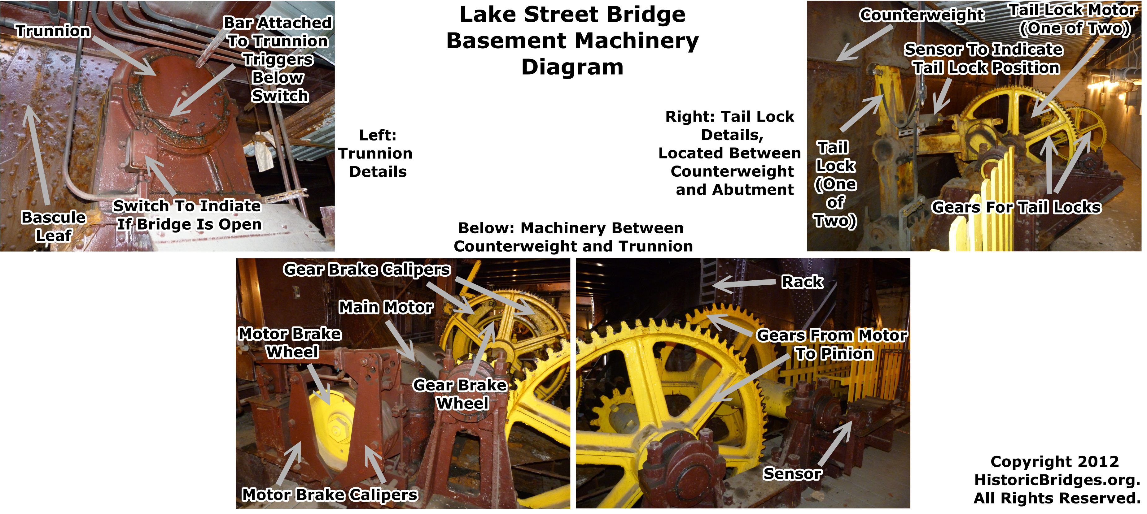
Scroll down to view photos for this portion of the gallery. The below diagram may be used as a reference in addition to the photo captions.
![]()

Looking directly south through machinery basement. These photos were taken in the west leaf basement.
![]()

Looking southeast through machinery basement toward motor. The trunnion girder is in the far background.
![]()
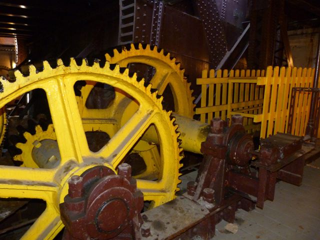
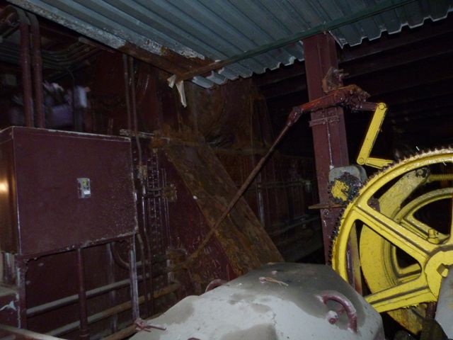
View looking southwest through machinery basement toward rack, visible in background.
![]()
View showing gears which link the motor to the pinion.
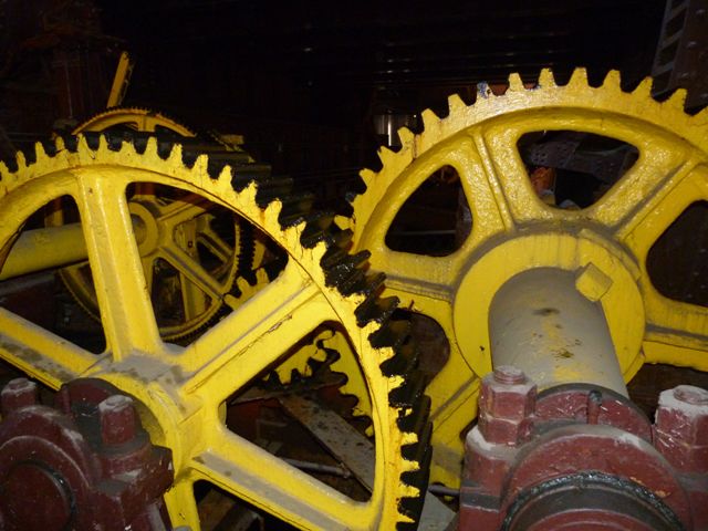
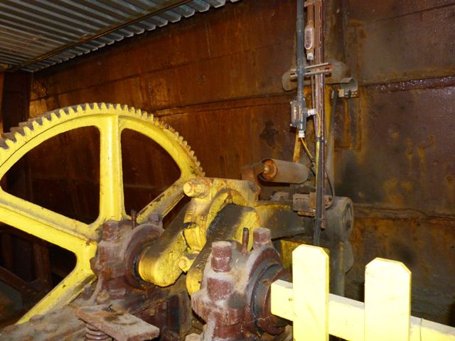
![]()

Looking toward a gear, with the braking system for the gears visible in the background.
![]()

Looking south through the western end of the machinery basement. Visible here is the tail locking system. The tail locking system has two motors available to power it. The use of two motors provides redundancy.
![]()


Gearing system for the tail locks.
![]()
Visible to the right in this photo of the tail lock system is a contact sensor to indicate that the locks are in or out.
![]()

View showing the actual tail lock, which is painted yellow, in its locked position, wedged into the counterweight.
![]()

View showing the motor. Two motors are available for lifting the bridge. If needed, the bridge can be raised under a single motor.
![]()

Braking system for the motor. The use of a braking system for both the motor and the gears provides greater safety and reliability through redundancy.
![]()

View showing the trunnion.
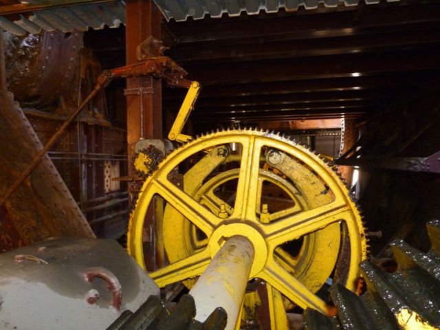
![]()
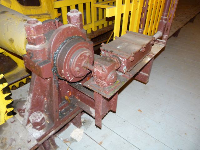
Sensor for the gearing system.
![]()

Details below the trunnion. The unused gears seen to the lower left are assumed to be the remains of the old leaf position indicator that remains on some of the Chicago bridges but has been lost on others. If so, this would have connected to an arrow that would rise above the roadway as a pointer to indicate leaf position.
![]()
Scroll down to view photos for this portion of the gallery. The below diagram may be used as a reference in addition to the photo captions.

![]()
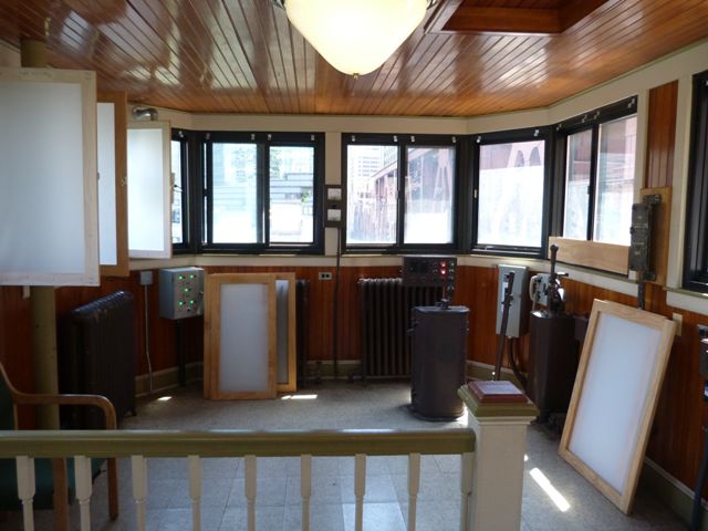


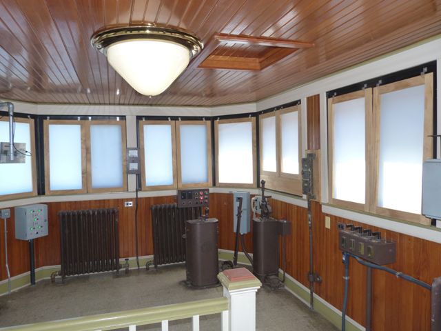

Looking east through control room.
![]()


Looking southeast toward bridge position controls.
![]()


Looking northeast toward CTA status indicator box.
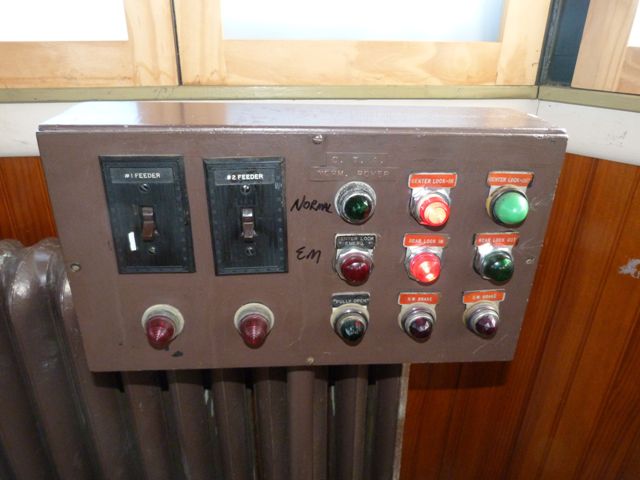
![]()


CTA status indicator, which relays bridge lock status to nearby CTA Control Tower.
![]()

Overview of controls and indicators in southeast corner.
![]()
Looking southwest toward additional bridge gate controls.
![]()


View looking east.
![]()

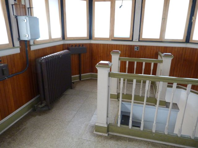
Looking south from stairway.
![]()

Looking southeast from stairway.
![]()


Looking northwest toward stairway.
![]()

Looking west toward stairway.
![]()

Window, ceiling, and light.
![]()
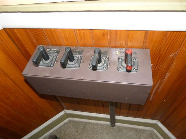
Gate switches in southwest corner of control room.
![]()

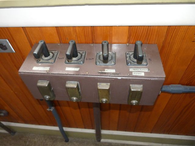


Gate and lock switches on south wall.
![]()


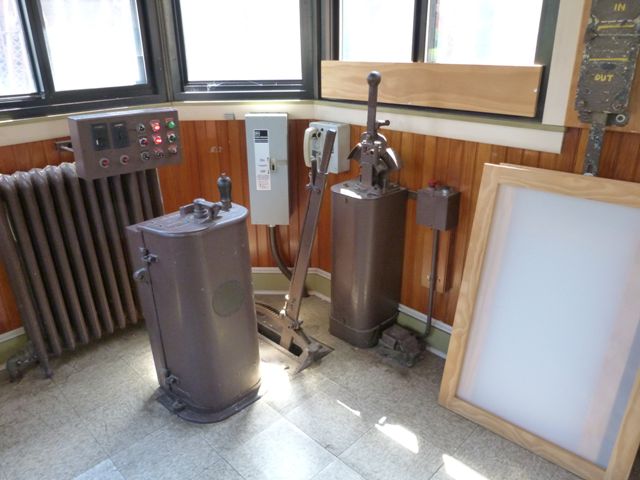
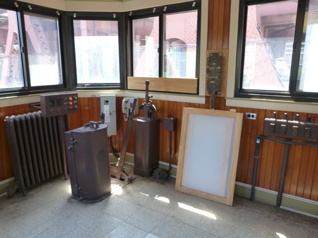
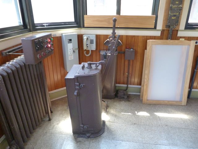
Auxiliary bridge position controller.
![]()


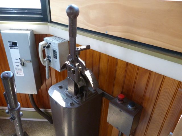
Shown in center, backup (hand) brake.
![]()


Primary position controller.
![]()

Electric brake foot switch, part of the primary position controller.
![]()

Voltmeters.
![]()


Lock position indicator.
![]()


Status indicators.
![]()
![]()

![]()