
Uncredited photos on this page taken by: Nathan Holth. Unless stated in a caption, all photos are Copyright with All Rights Reserved. Learn about reuse of our photos.
![]()


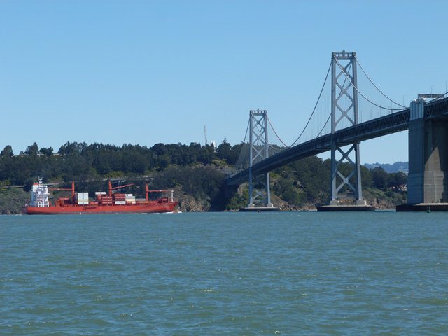
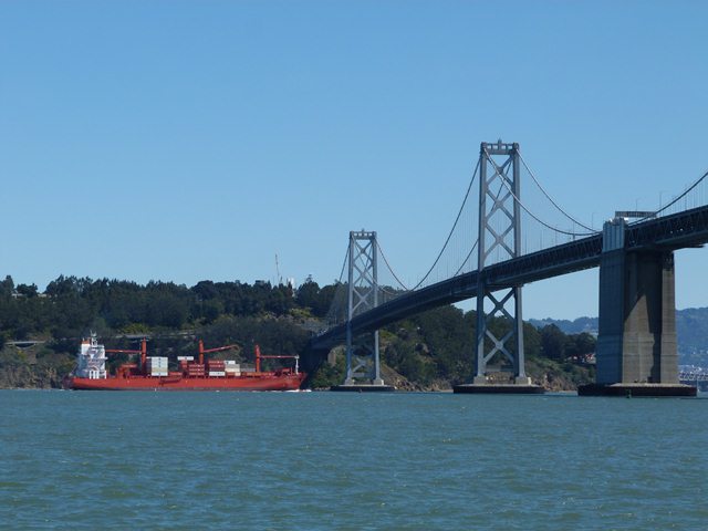
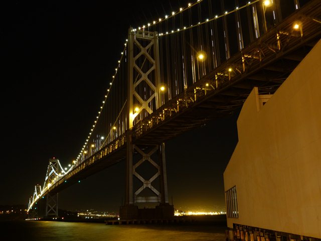
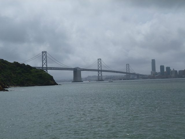
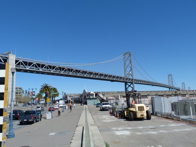
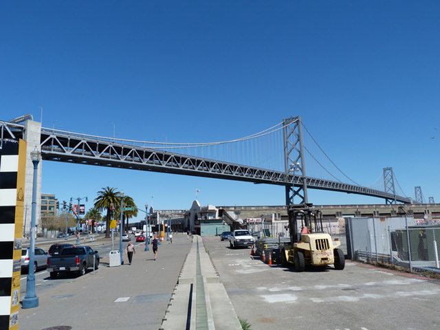
Views beside bridge from northwest quadrant.
![]()


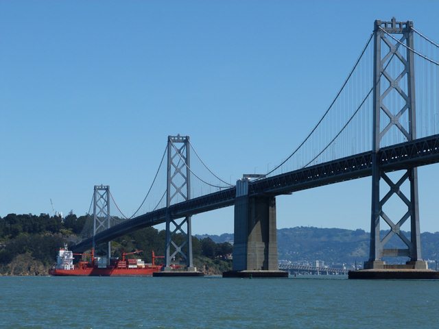
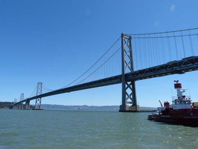
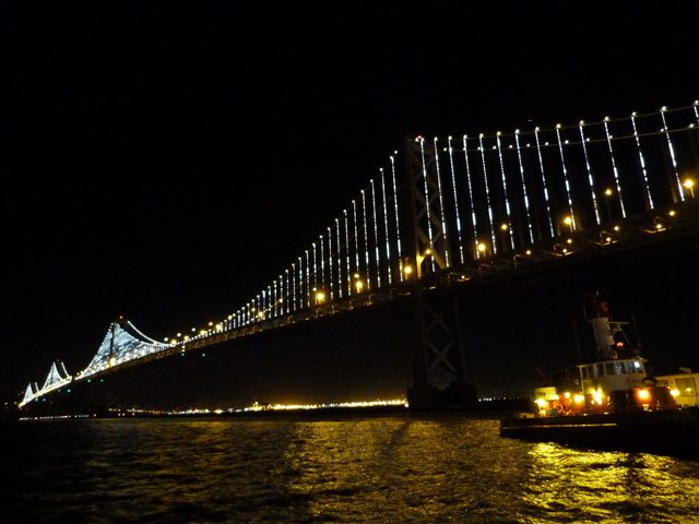
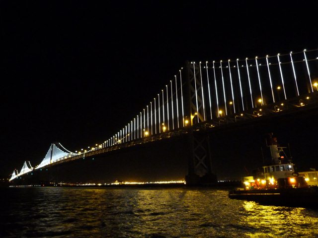
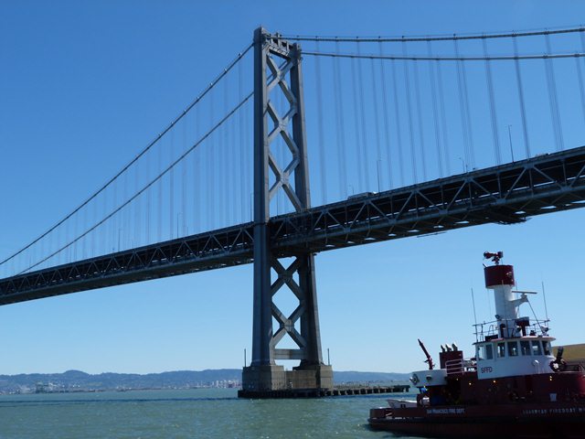
Freighter passing under bridge, viewed from northwest quadrant.
![]()


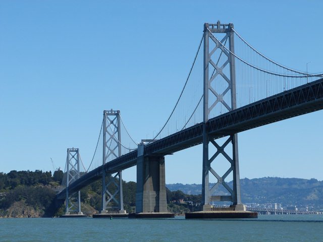
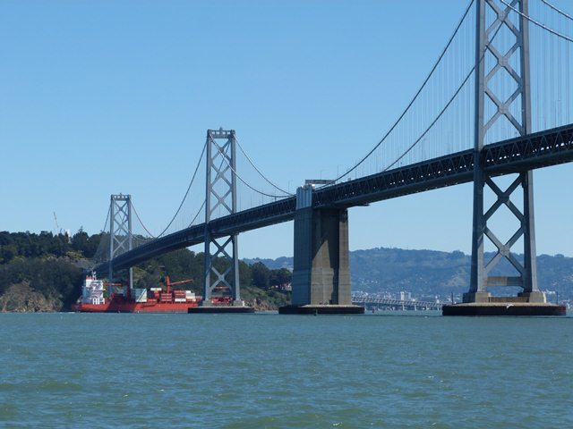
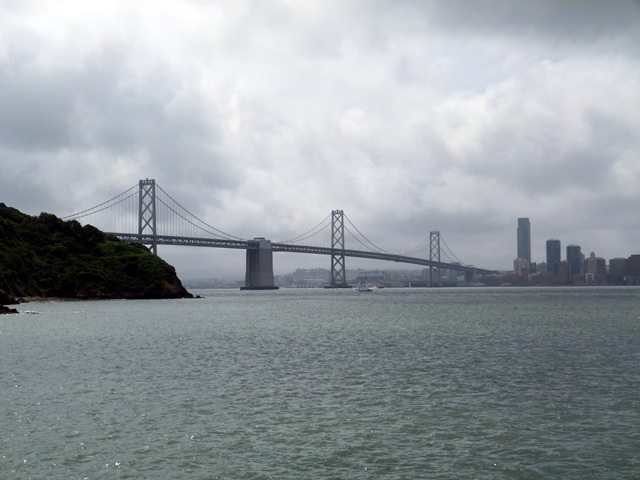
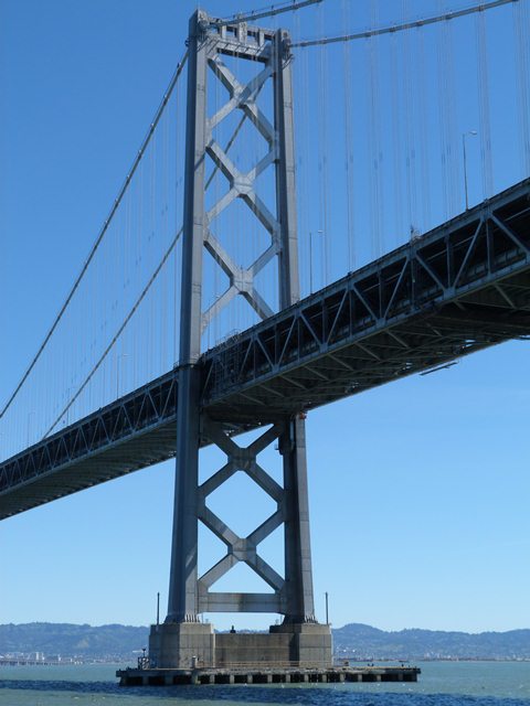
Elevation from northwest quadrant.
![]()


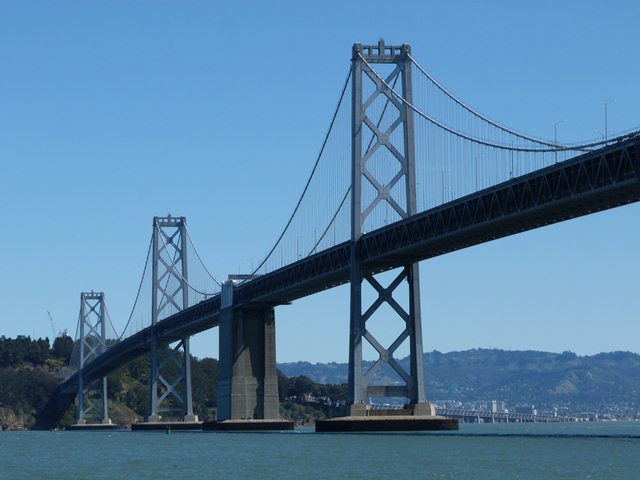
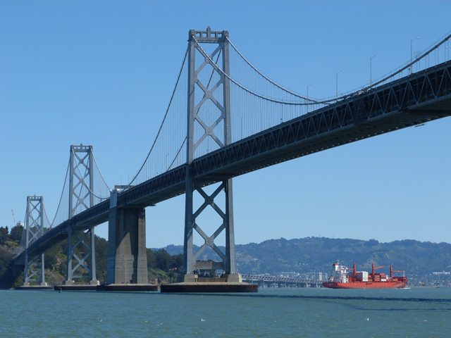
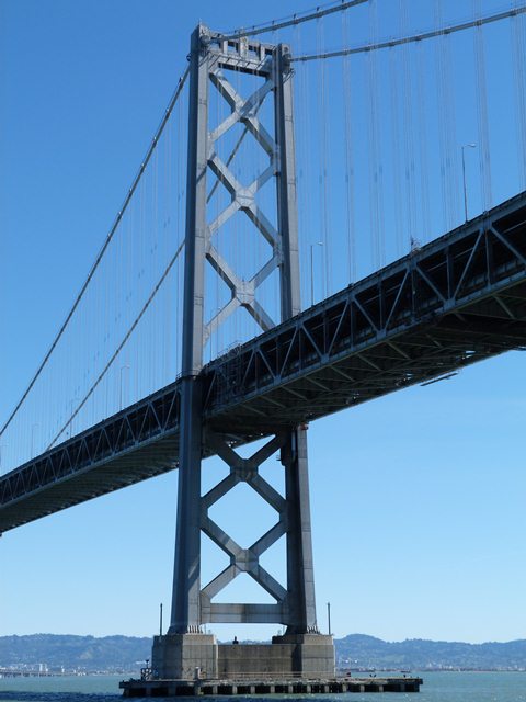
Elevation of westernmost suspended span.
![]()
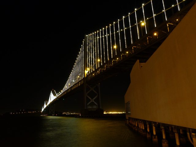

Night views beside the bridge.
![]()

Elevation from northeast quadrant, on Treasure Island.
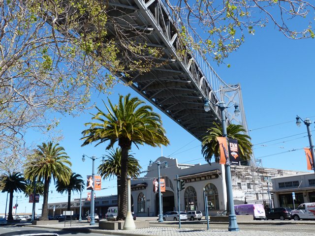
![]()

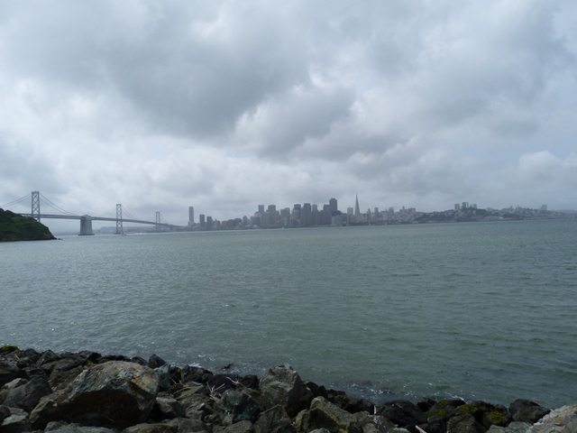
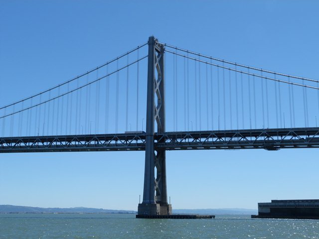
View beside bridge from southwest quadrant.
![]()
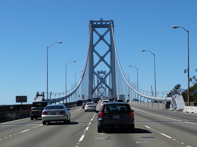

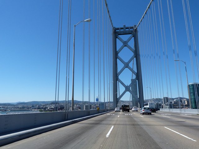
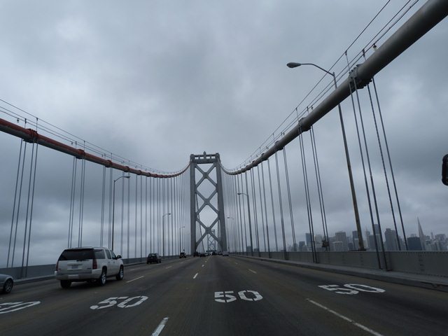
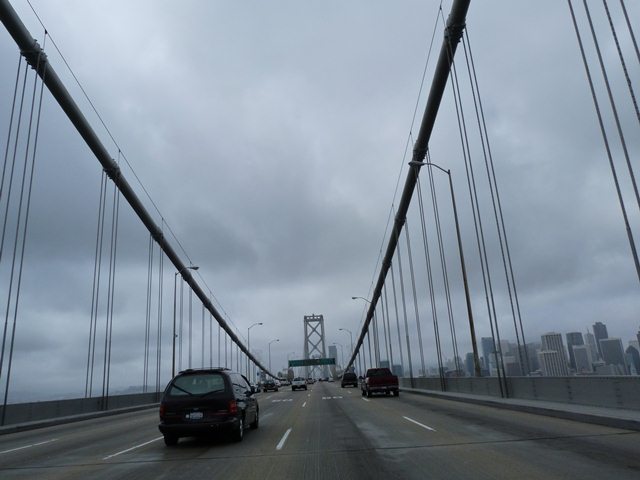
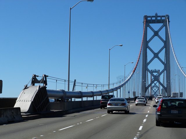
Suspension bridge portal views facing west during a sunny day.
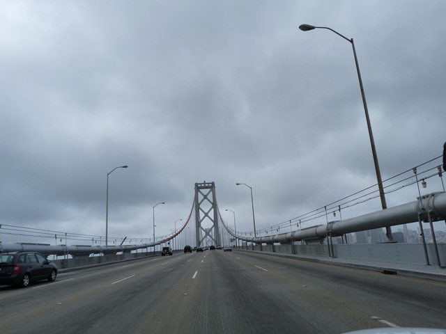
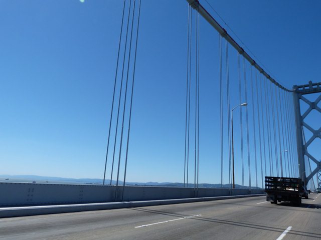
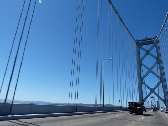
![]()


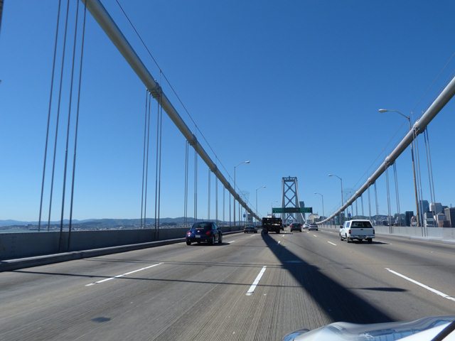


Westbound portal views on bridge during a sunny day.
![]()


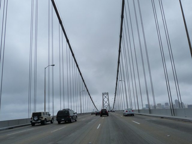
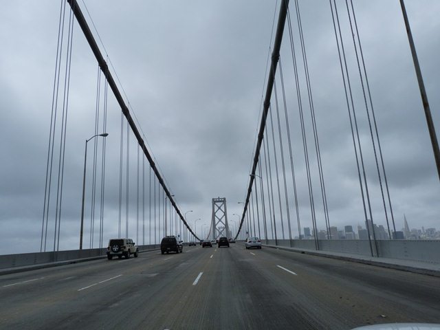

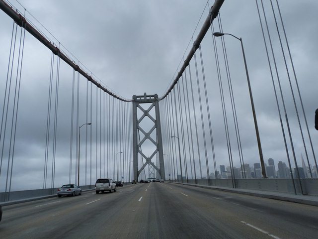


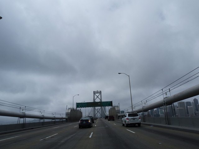
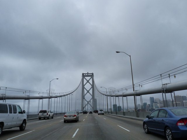
Westbound portal views on eastern suspended spans during a cloudy day.
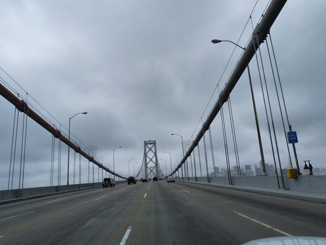
![]()
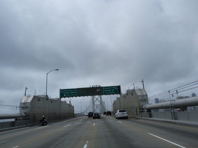
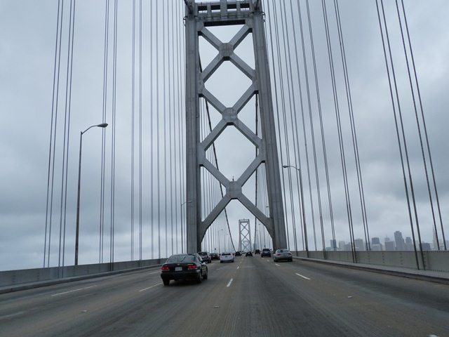
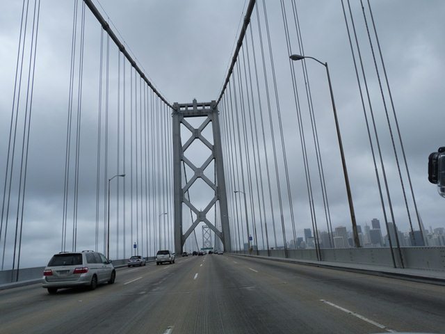
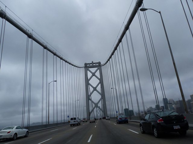
Westbound portal views on bridge showing center anchorage during a cloudy day.
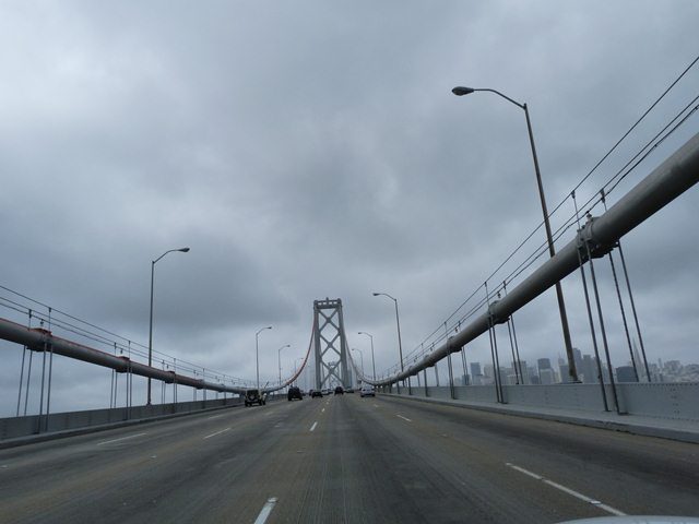
![]()
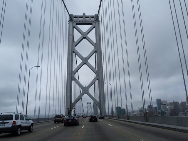


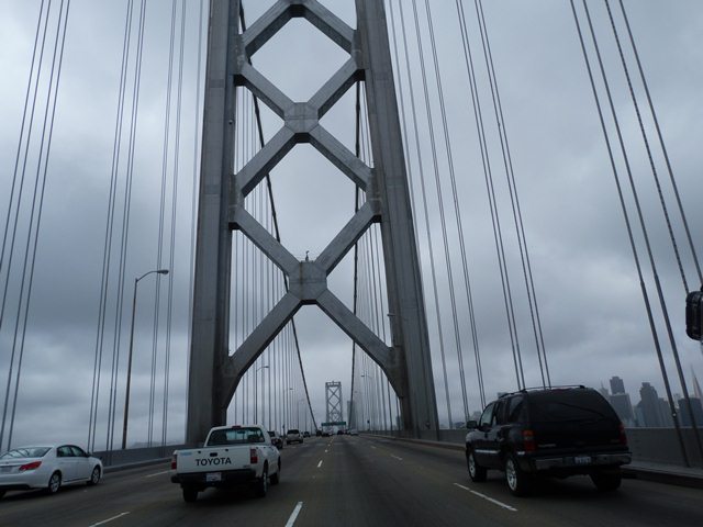
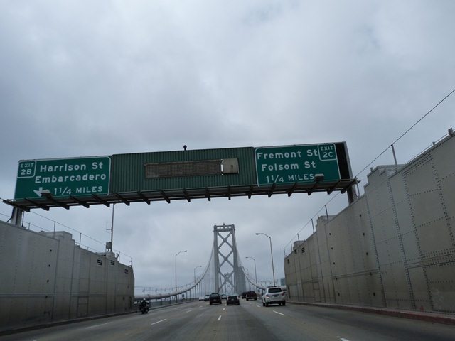
Westbound portal views on western suspended spans during a cloudy day.
![]()

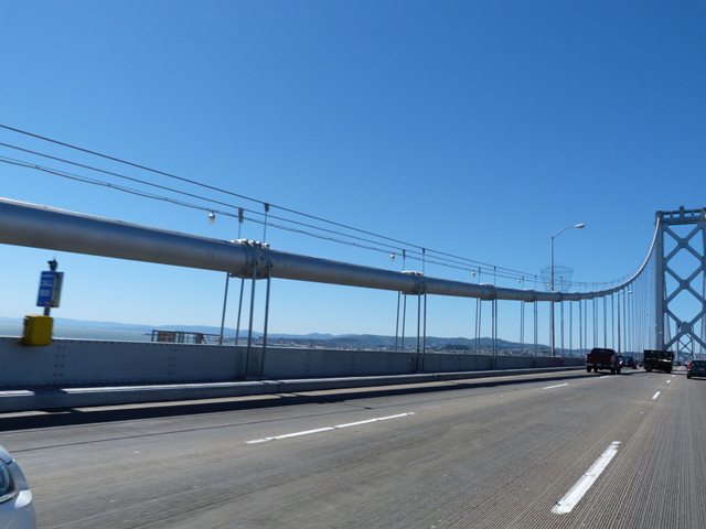
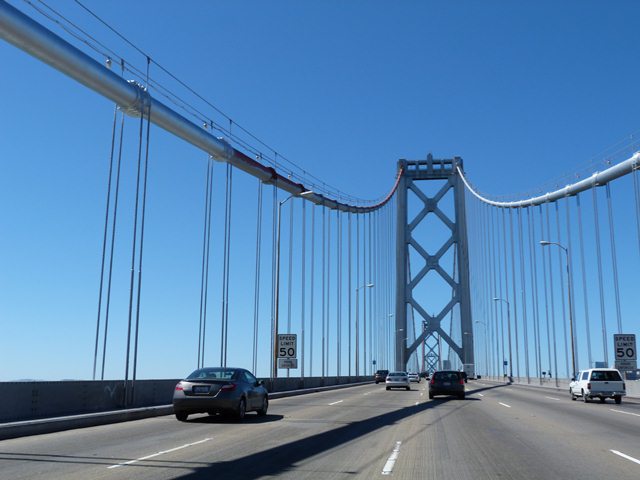
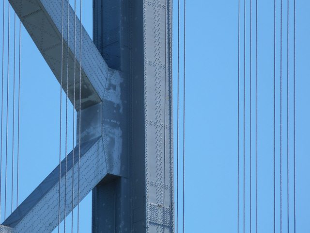
Main cable and suspender cables as seen from on bridge.
![]()


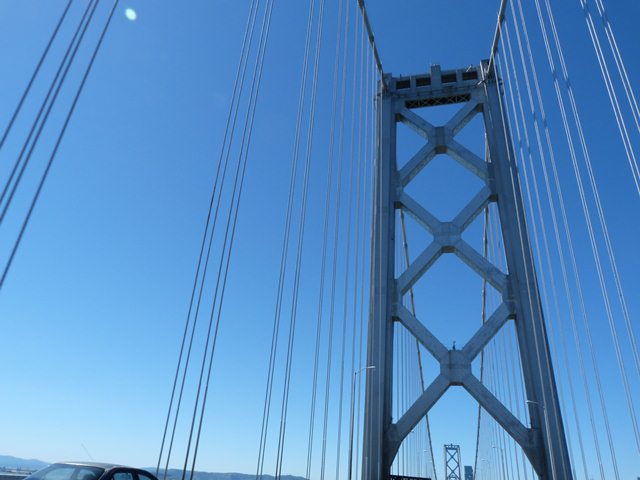
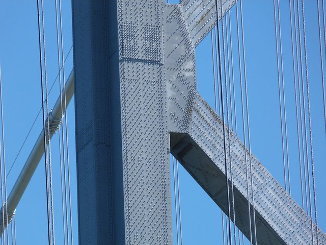
Towers as seen from on bridge.
![]()


Towers as seen from beside bridge.
![]()
Main cable saddle enclosure.
![]()


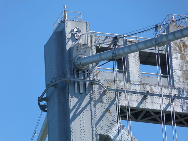
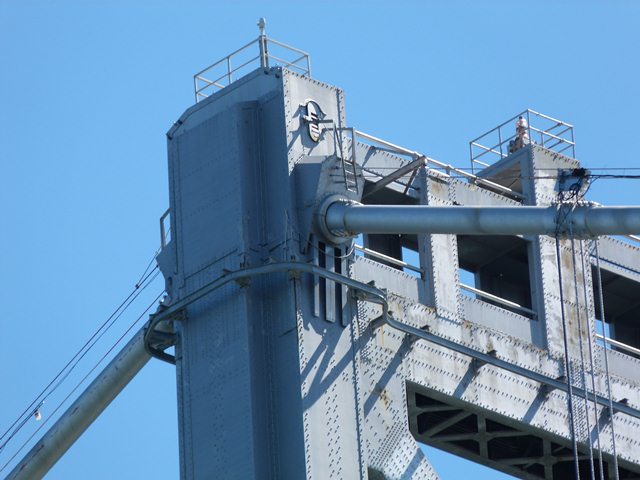
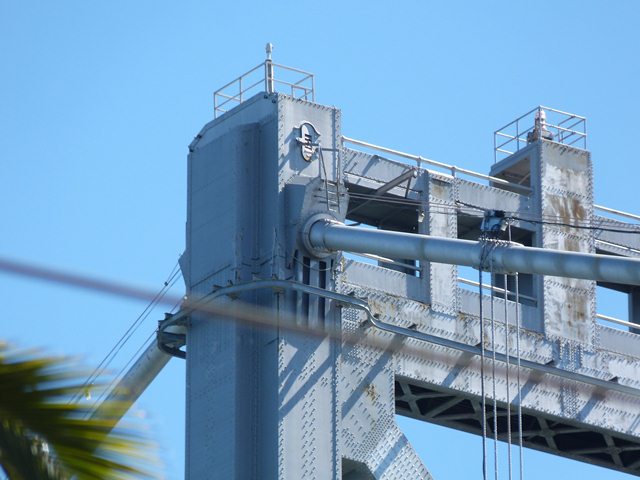
Details at top of tower.
![]()


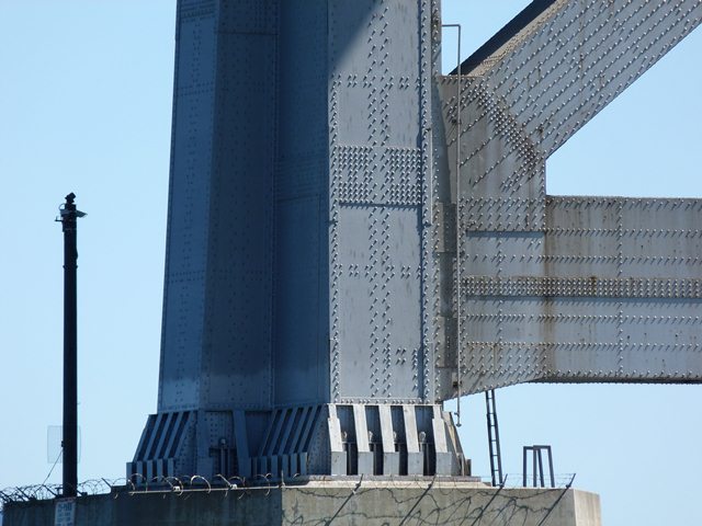
Detail at base of tower.
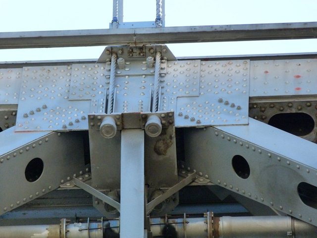
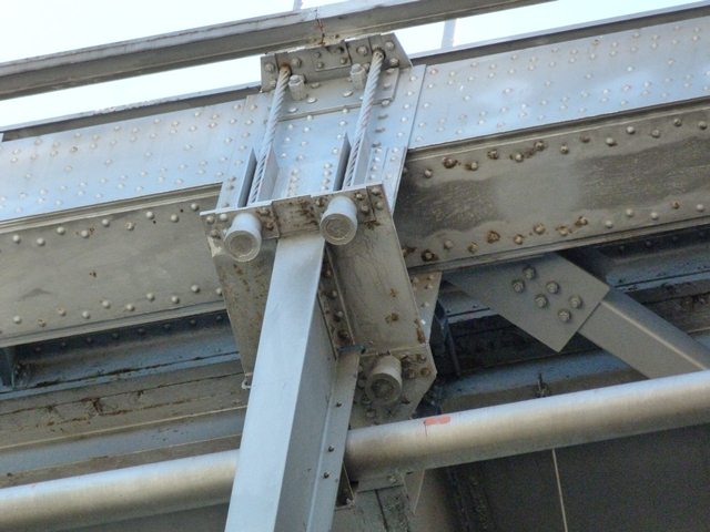
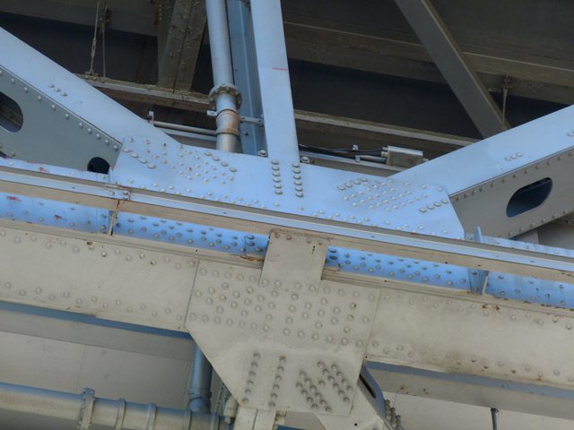
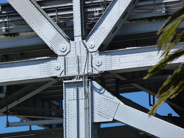
![]()
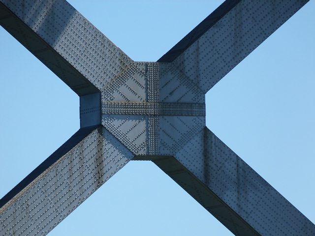


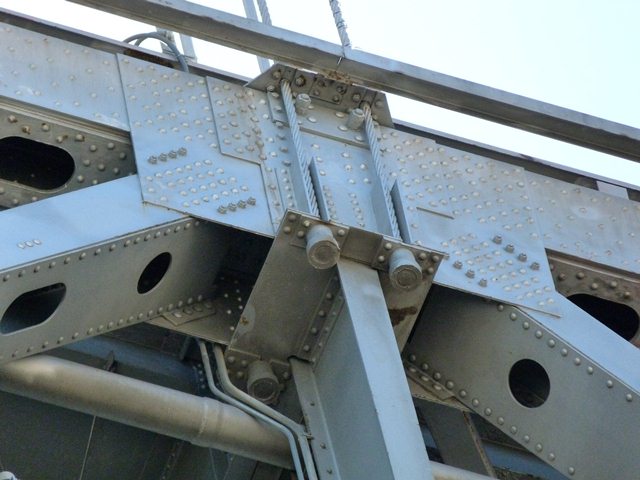
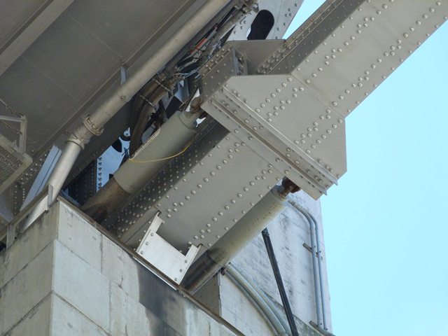
Tower bracing connections.
![]()


Tower post details.
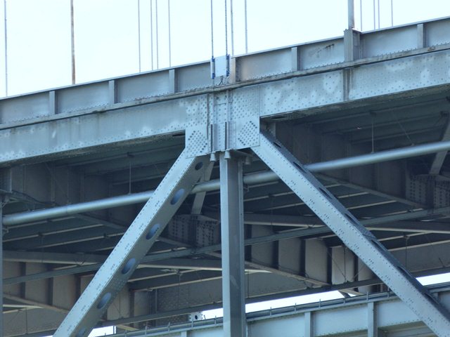
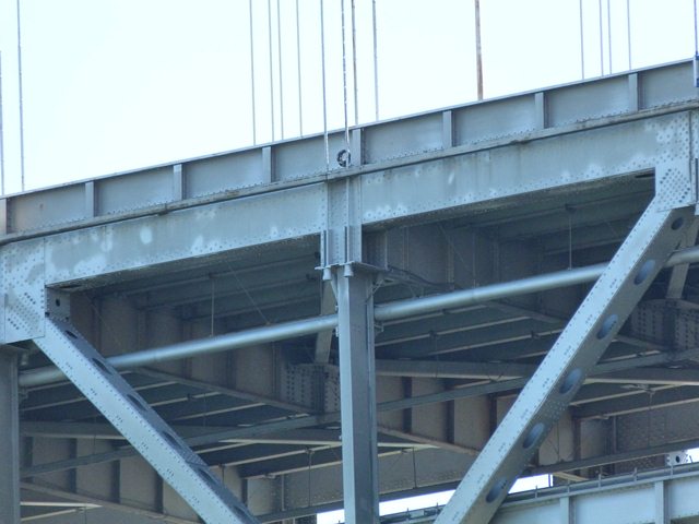
![]()


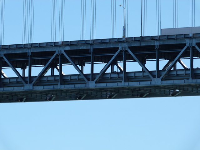


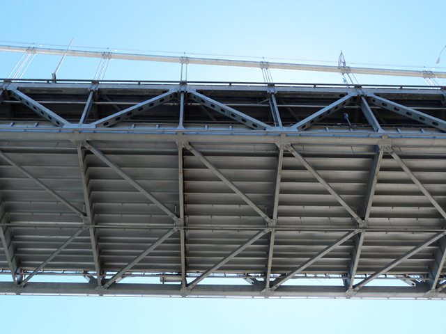
Stiffening truss.
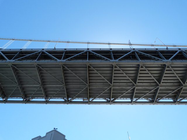
![]()

Western deck truss spans.
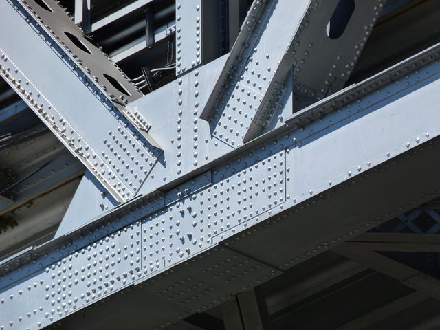
![]()


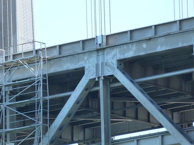

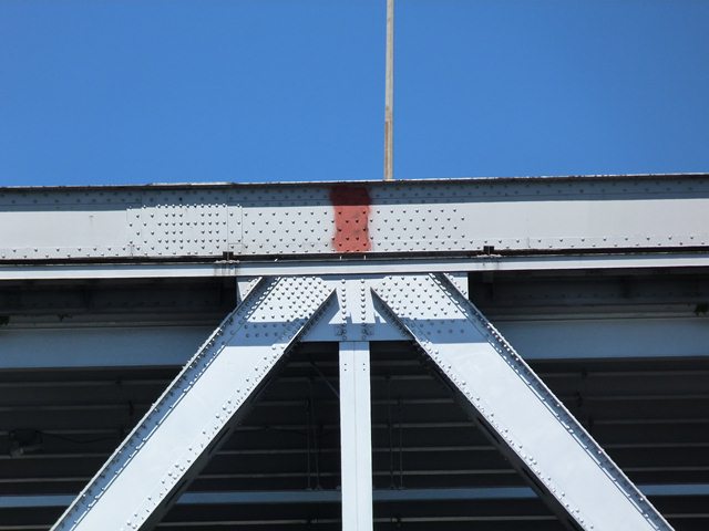
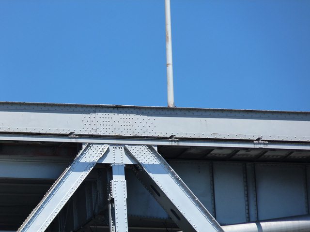
Stiffening truss top chord connections.
![]()
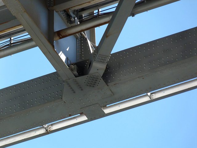
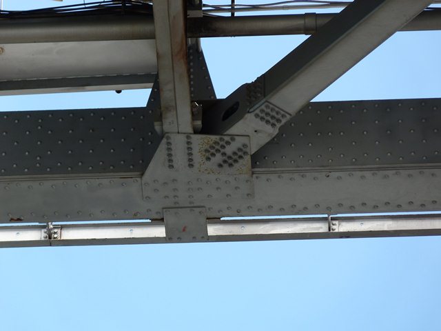
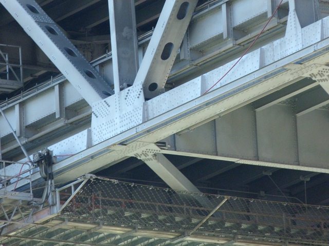
Stiffening truss bottom chord connections.
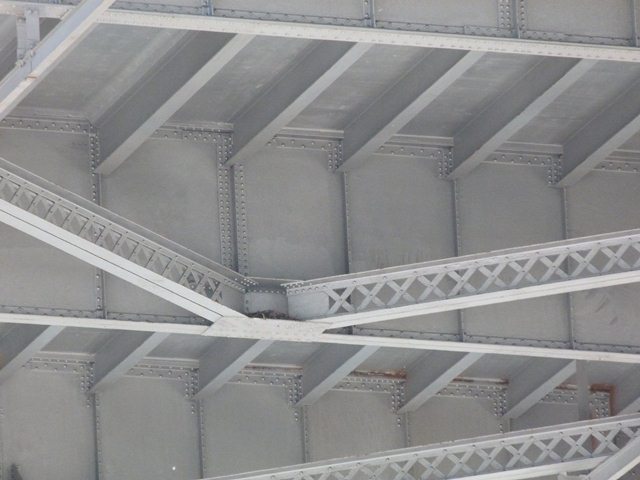
![]()

Deck truss top chord connections.
![]()

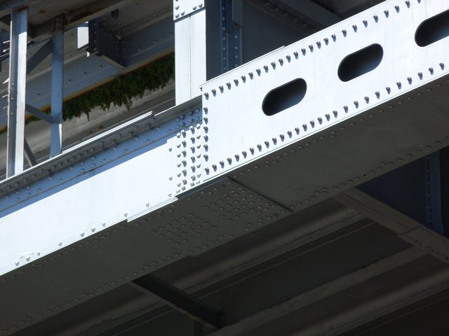

Deck truss bottom chord connections.
![]()

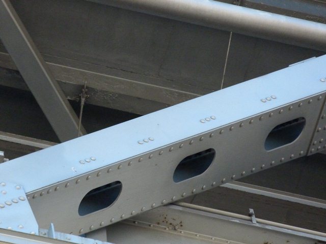

Stiffening truss diagonal members.
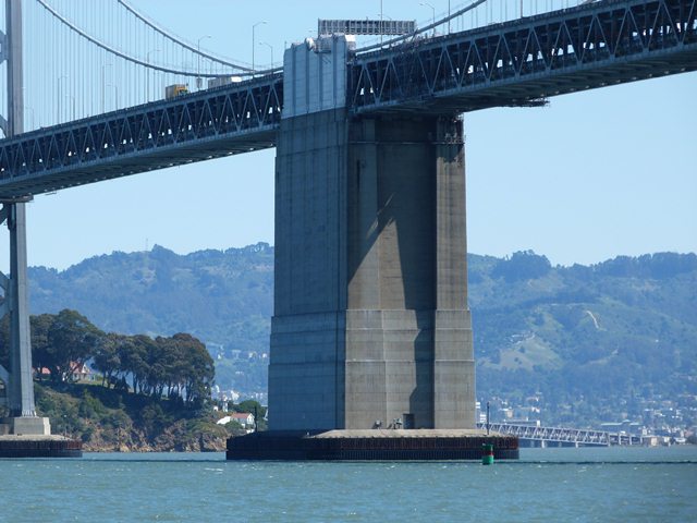
![]()


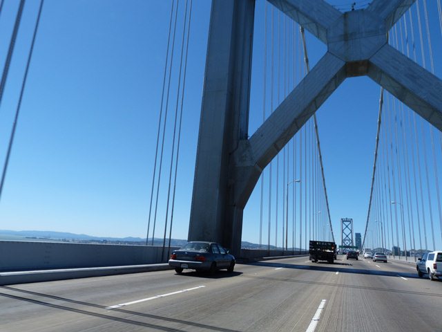
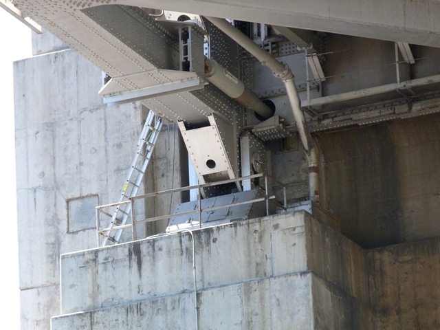
Pier at cable bent.
![]()


Center anchorage.
![]()

Western anchorage.
![]()

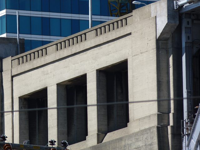
Western anchorage details.
![]()

Main cable detail at western anchorage.
![]()
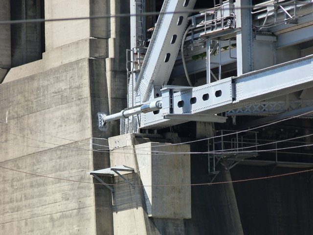
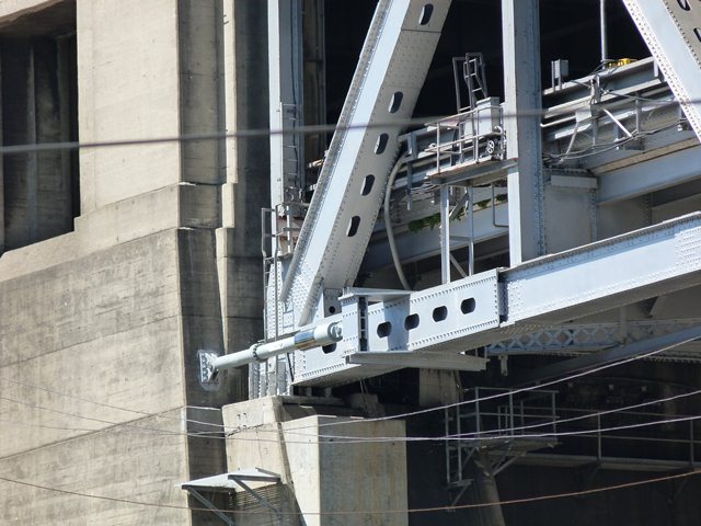


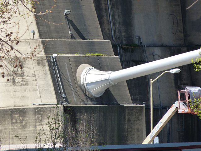
Bearings and earthquake shock absorbers.
![]()


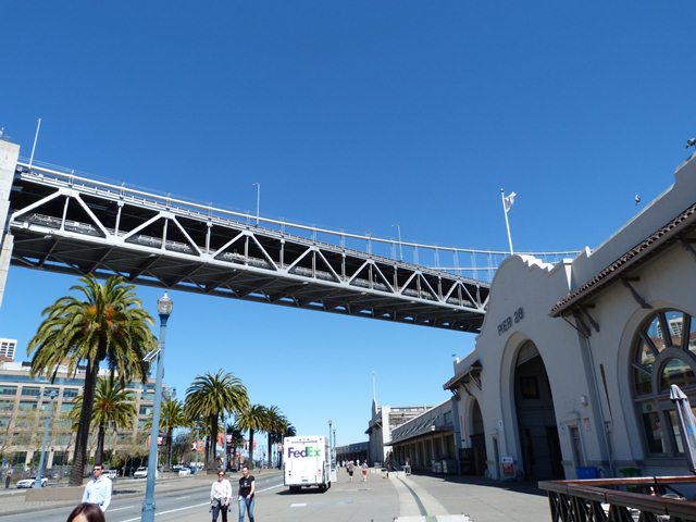
Views under western spans.
![]()


Flooring system details.
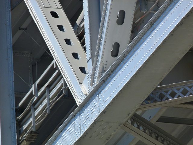
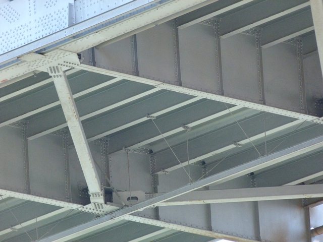
![]()

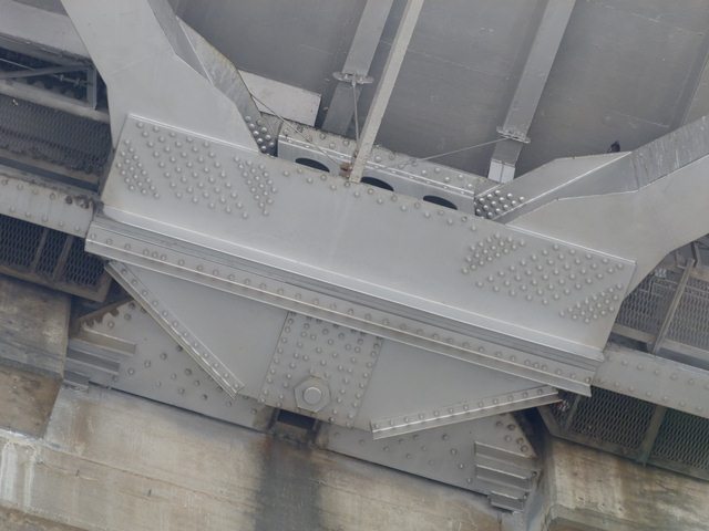

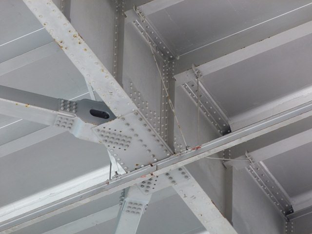
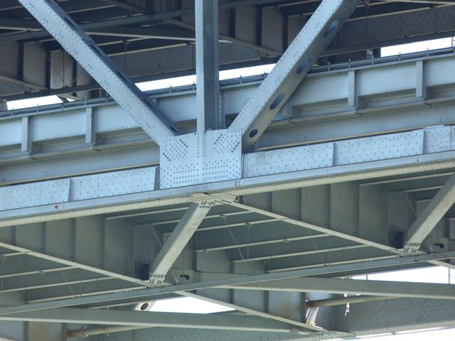
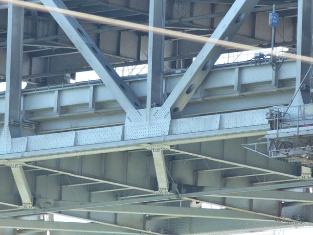
Bracing details under deck.
![]()


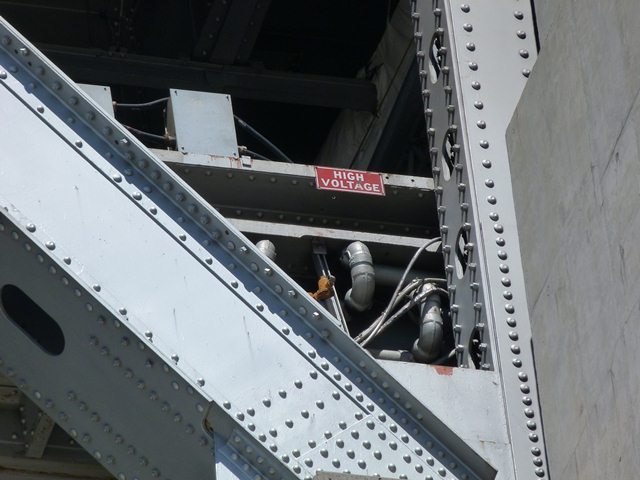
Utility lines on bridge.
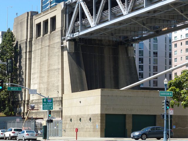
![]()

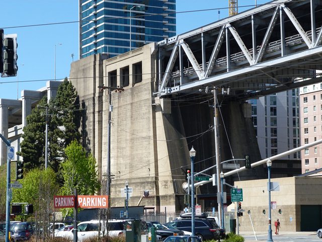
Bay Bridge Pump station at western end of bridge.
![]()

Photo Credit: Historic American Engineering Record
Aerial view of bridge.
![]()


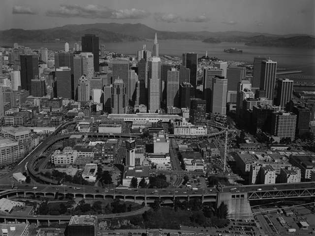

Photo Credit: Historic American Engineering Record
Aerial view of approach system at western end of bridge prior to alteration.
![]()

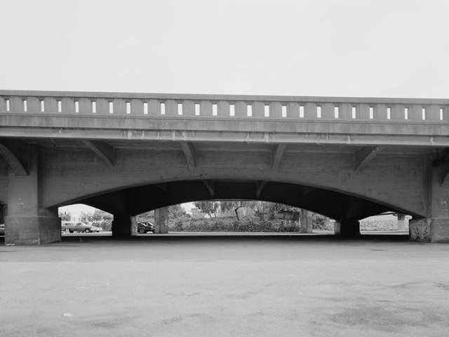
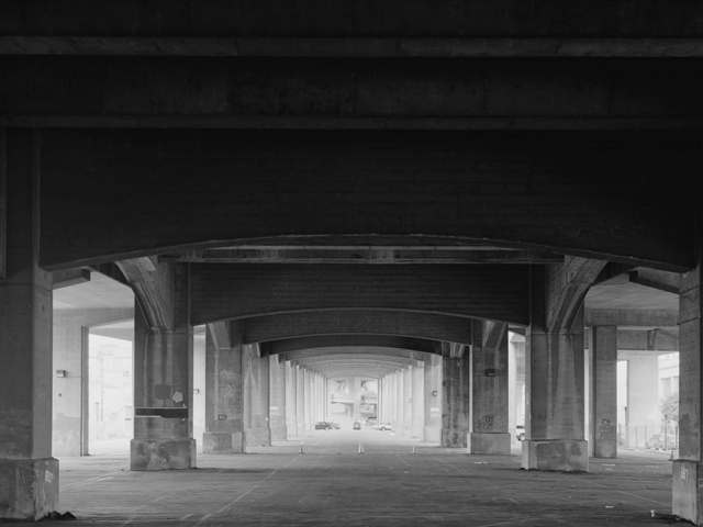
Photo Credit: Historic American Engineering Record
Views of the former approach system which has been altered and/or replaced.
![]()

Photo Credit: Historic American Engineering Record
Detail of cable band.
![]()

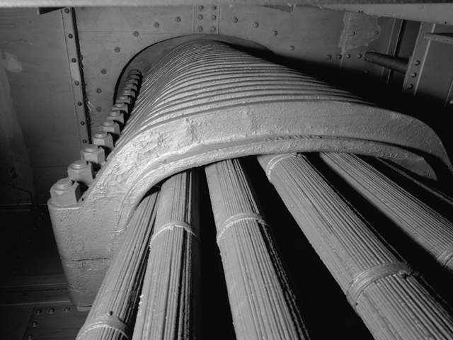
Photo Credit: Historic American Engineering Record
Main cable, splayed strands inside anchorage.
![]()


Photo Credit: Historic American Engineering Record
Splayed strands of main cable attached to the anchor eyebars.
![]()

Photo Credit: Historic American Engineering Record
Detail of a main cable attachment to anchor eyebar.
![]()
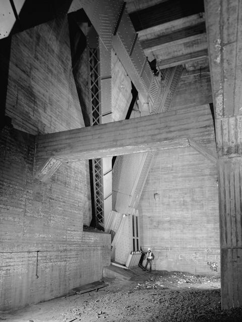
Photo Credit: Historic American Engineering Record
View showing cable bent strut.
![]()
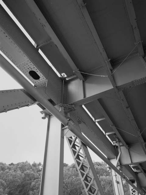
Photo Credit: Historic American Engineering Record
Stiffening truss detail prior to alteration
![]()
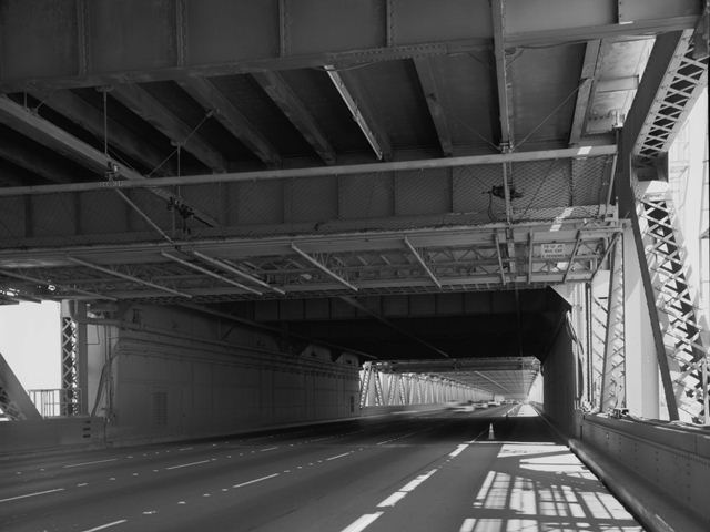
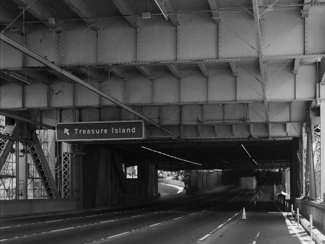
Photo Credit: Historic American Engineering Record
Lower deck prior to alteration of stiffening truss.
![]()
![]()

![]()