
Uncredited photos on this page taken by: Nathan Holth. Unless stated in a caption, all photos are Copyright with All Rights Reserved. Learn about reuse of our photos.
![]()


View of lowest level of bridge tender house.
![]()


Middle levels of bridge tender house.
![]()

Top level of bridge tender house.
![]()


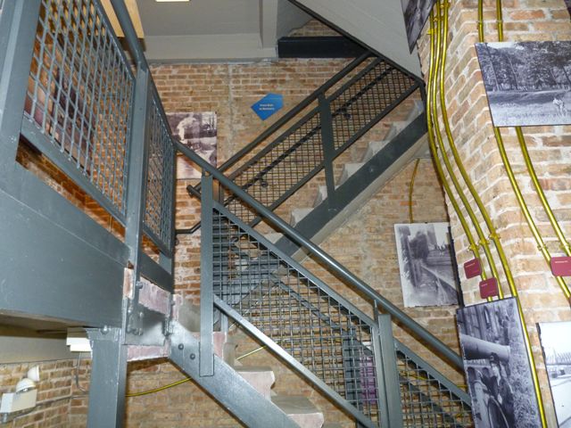


Stairways.
![]()


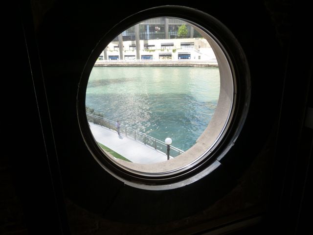

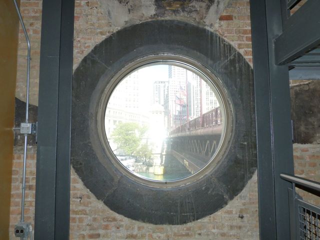

Views showing the large circular window.
![]()
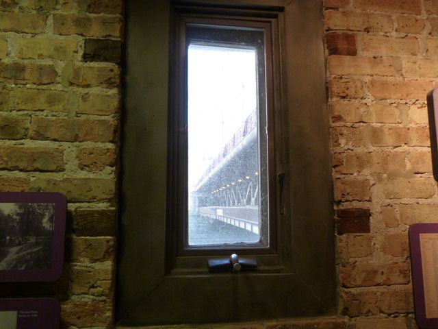


Additional windows.
![]()


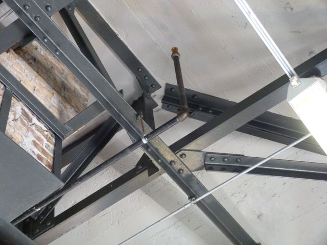


Riveted roof trusses as seen from top level.
![]()

Ceiling.
![]()


Riveted structural support beams.
![]()
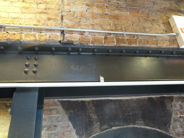
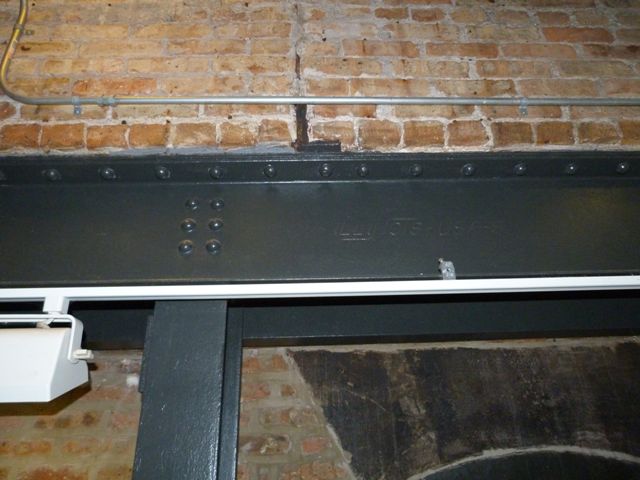
Illinois brand on riveted structural support beams.
![]()

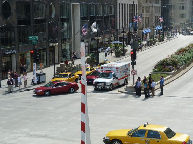


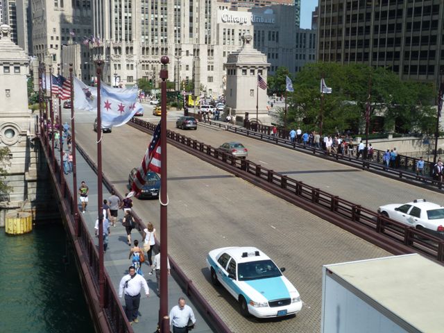
Looking south down Michigan Avenue from top level of bridge tender building.
![]()

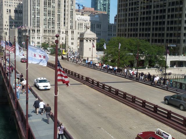

Looking northbound up Michigan Avenue from top level of bridge tender building.
![]()

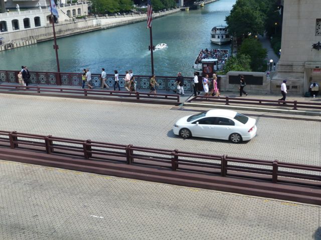

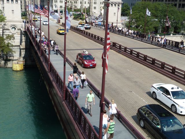
Looking down at the bridge deck from top level of bridge tender building.
![]()

Southeast bridge tender building as viewed from the top level of the southwest bridge tender building.
![]()

Overview of part of the room which is essentially the inside of the bridge and includes the drive system and the counterweight tail pit.
![]()

Bridge interior: View showing rack with gear in foreground.
![]()
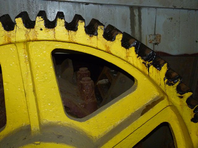
Bridge interior: In the foreground is a gear that is part of the drive system that connects to the pinion. The rack and pinion are visible in the background through the hole in the big gear.
![]()

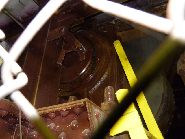


Views of the main trunnion.
![]()
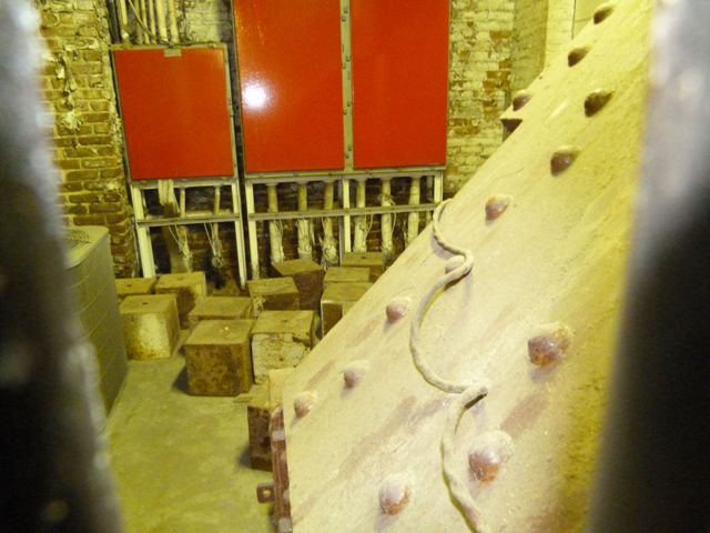
Extra counterweight blocks being stored. Changes in the weight of the bridge due to repairs and other variable conditions sometimes require the adjustment of the counterweight system.
![]()


Detail photos showing the end of the bascule leaf which would include the counterweight.
![]()
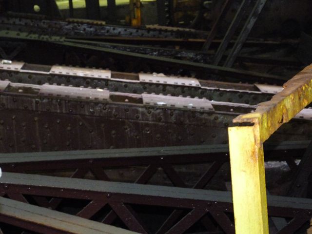
View of the trusses leading up to the very end of the bascule leaf and counterweight.
![]()


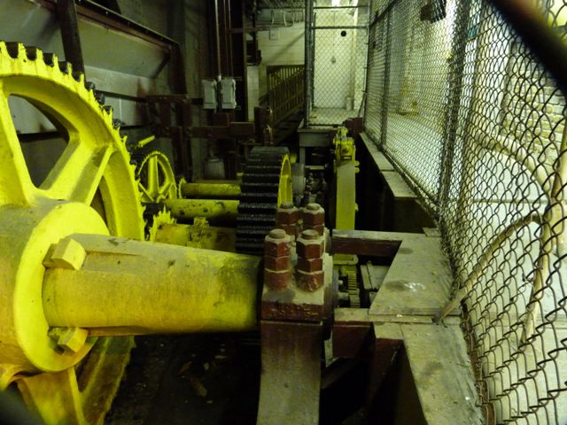


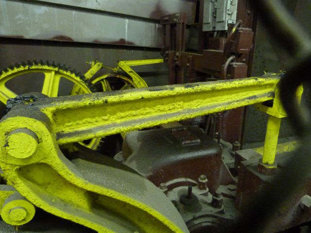
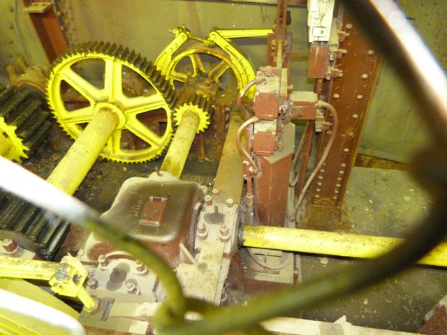

Various views showing the gearing and braking system, located alongside the rack and pinion.
![]()


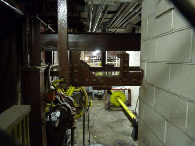


Views showing the very back of the room where the motors and additional gearing is located.
![]()
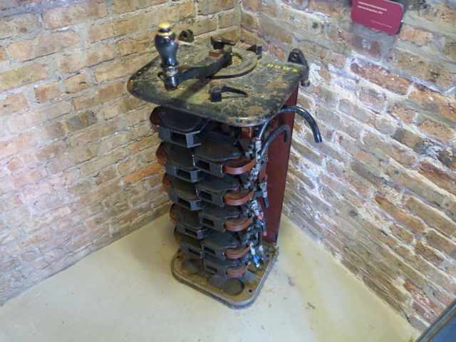


Exhibit, the old throttle control for controlling the speed during lifting and lowering the bridge.
![]()


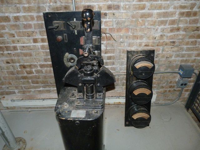


Photo Credit: Historic American Engineering Record
Exhibit, additional bridge/electrical controls and meters.
![]()


Photo Credit: Historic American Engineering Record
Views inside operable bridge tender house control room.
![]()


Photo Credit: Historic American Engineering Record
Machinery basement.
![]()

Photo Credit: Historic American Engineering Record
Trunnion and trunnion girder.
![]()
![]()

![]()