

View Information About HSR Ratings
| Additional Technical Facts |
| Main Span Lengths (In Feet) | Minimum Railroad Underclearance | Vertical Clearance | Skew Angle | Total Main-Span Length | Approach Span Details |
| 5 172 Foot (52.4 Meter) spans, 1 187 Foot (57 Meter) span, and 3 246 Foot (75 Meter) spans. | 21.82 Feet (6.6 Meters) | 14.73 Feet (4.5 Meters) | 19 Degrees | 1908 Feet (581.6 Meters) | 8 pre-stressed concrete continuous totaling approximately 209 Feet |


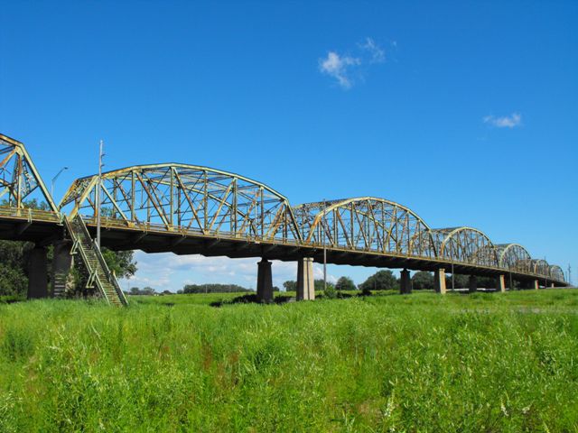
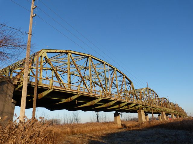
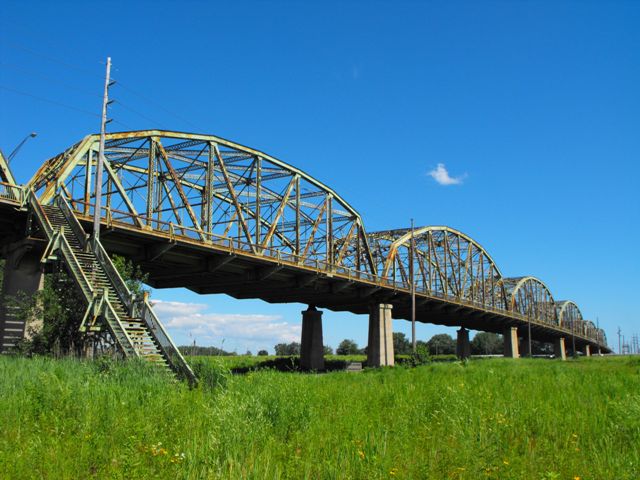
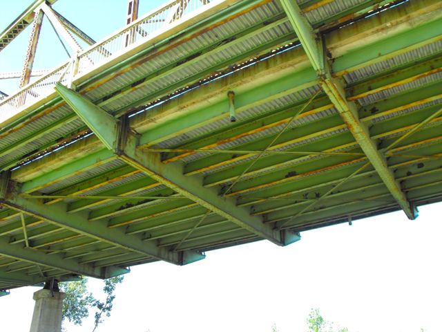
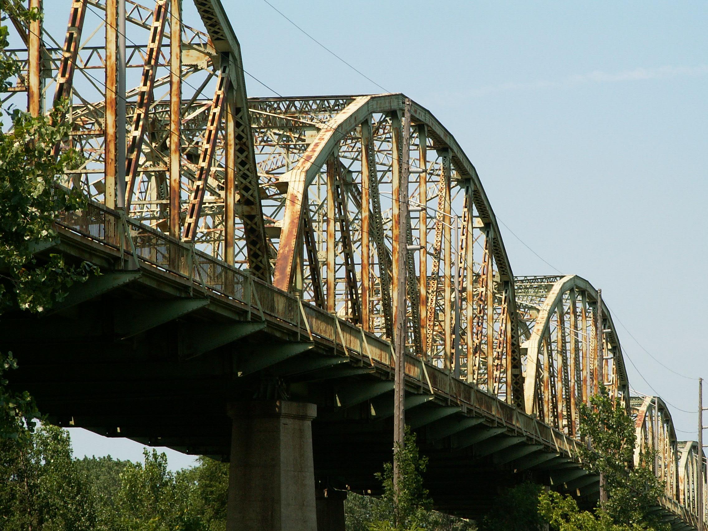
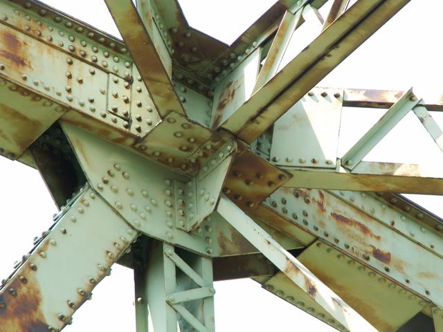
This extremely long bridge has a length comparable to Ohio River bridges such as Ohio's Market Street Bridge. It is also a wide truss bridge, apparently originally a four-lane structure. Today it has two lanes, with a bike lane on the east side, and a small shoulder on the west side. This bridge does not achieve its long length via some complex cantilever span, but instead utilizes a series of simple spans composed of Parker through truss spans instead. They feature riveted connections. The railings on the bridge appear to be original. There is extensive v-lacing and lattice present on the bridge thanks to widespread use of built-up beams, which adds to the aesthetic value of the bridge, and there are also some members featuring battens as well. There are Inland steel brand marks on the bridge. The bridge is composed of nine spans of varying size. Although the spans at each end of the bridge are not skewed and have a traditional appearance, the remaining seven spans in between have a significant skew to them. There are different ways that engineers configured skewed trusses. With this bridge, the approach was extremely bizarre, since the engineers designated variable depth portal bracings that resulted in portal designs that boggle and trick the mind when viewed. Even more unusual is the actual truss webs, which on the skewed spans are designed such that the height of the end post at one end is higher than the length of the end post at the other end. The result is an asymmetrical truss that looks very strange when looked at carefully.

The result is a bridge whose skewed spans are individually interesting and should be considered historically and technologically significant, but also combine to form a bridge that is a monumental-sized landmark for Hammond and is historically and technologically significant as a long and complicated engineering achievement. The bridge is also significant as one of the most complex bridge engineering projects ever designed by the Indiana State Highway Commission. The unusual site requirements meant that a standard plan bridge would not suffice, and so this bridge had to be designed from scratch, with all its unusual details. As such, it is one of the best representative examples of Indiana bridge engineering.
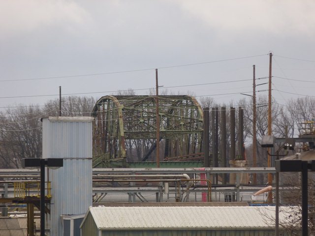
This bridge can be seen from the I-90 Indiana Turnpike as you head toward Illinois, and similarly from the parallel Southshore commuter trains, with the bridge's striking spans leaping across the rail yard in the distance. The bridge is so long, and has a camber to the deck, meaning that a driver cannot see one end of the bridge from the other end, making it initially look like a truss bridge that goes on forever. The bridge is a thrill to walk or drive across. The exceptionally wide lanes and shoulders also make the bridge very comfortable for drivers as well.

Despite the extremely high level of historic, technological, and aesthetic qualities of this historic bridges, InDOT is demolishing and replacing this bridge. Whether they rehabilitated or replaced it, a fair amount of money was going to be spent on the bridge due to its size. Replacement incurs additional costs for removing such a large structure. Often, replacing a bridge costs more than restoring it! Why not save demolition costs and use this money towards preserving this historic landmark?
The replacement bridge will apparently offer four lanes for traffic. While this might sound like a great idea, it was not apparent that any significant increase in efficiency will be realized. Despite how busy the bridge is, traffic seemed to move fine across the bridge. Even with stoplights at both ends, and an active at-grade railroad crossing south of the bridge, traffic did not back up excessively.

Many historic bridge experts often state that Indiana has one of the best records for preserving historic metal truss bridges. This is a reasonable statement in regards to local highway agencies and other local organizations in Indiana who have preserved historic truss bridges either for vehicular or pedestrian use. However InDOT has done little to preserve the historic truss bridges under its jurisdiction. Furthermore, the rarest and most significant bridges like this one are targeted for demolition. The few examples of preserved InDOT owned bridges tend to be historic bridges of lesser significance. Still significant, but not enough to justify the loss of landmark historic bridges like this one.
This bridge has been locally known as the Nine Span Bridge, a descriptive title for the bridge. With its demolition and replacement, this name will lose its meaning since the replacement bridge only has eight spans. Furthermore, calling the replacement bridge a "bridge" would be insulting to the engineers who designed the historic bridge. The replacement bridge will be so simple and ugly that it would defy description in any human language. Where crossing the historic bridge is an exciting experience of crossing a visually prominent landmark, the replacement structure will have the appearance of nothing more than a slab of concrete. The bridge will be so ugly that even Matt Deitchley of InDOT, the agency that is promoting this demolition and replacement project had no alternative but to admit that the bridge will be nothing worth noticing. Describing the replacement bridge, he was quoted in a WBEZ interview as follows: "It's not going to look anything like it looks now: the iconic look of the bridge now with the trusses above. It's going to be more of a standard, pavement like you normally seen. So, not a very artistic, old school type of bridge. It's going to be more like one of the newer type of bridges that you're seeing around the area."
InDOT would do well to look to its neighbor, Chicago, Illinois and see how CDOT has chosen to preserve its historic bridges, and thus find inspiration to preserve the Indianapolis Boulevard Bridge. At the same time that InDOT moved to demolish this bridge, CDOT continued work on rehabilitating the nearby Torrence Avenue lift bridge.

The Memorandum of Agreement for the demolition of this historic bridge states that one of the spans of this bridge will be dismantled and stored for a period of 10 years from the time of demolition. The span that is being dismantled and stored is the third span from the south. The stairway attached to the northern end of this span will be saved as well. The span is 172.5 feet in length. While it lacks the unique nine span length of the original bridge, this salvaged span includes the unique skewed design that made this bridge unique. The bridge is available to any third party whose proposal to relocate and preserve it is accepted by the State Historic Preservation Office. Its wide width for a bridge of its age as well as its massive members would make it a great candidate for reuse on a rural road, where the bridge is wide enough that it likely meet current standards for a rural road. It also would be useful for a non-motorized crossing, perhaps a busy trail system that is used by both bicyclists and pedestrians. Its width would allow for lanes to divide the forms of non-motorized traffic. It would even have room for benches, accommodations for people fishing from the bridge, informational kiosks. A portion of the deck could even be turned into a flower garden. This salvaged span is a chance to preserve a small part of this beautiful historic bridge. It is a chance for someone to do what InDOT lacked the vision to do, which is to see the potential this span has for rehabilitation and reuse. However, if nobody steps forward to reuse the span by 2023, this stored span will join its eight other truss spans in the scrapyard, and every bit of this unique historic bridge will forever destroyed and lost forever.
Learn more about this span's availability here.
Information and Findings From DHPA Historic Bridge SurveyDescription of Bridge A year after the ISHC had an overpass of two railroads built in Lake County (#1030), it contracted for an even more complex railroad overpass. This one involved eighteen spans on a 19-degree skew, carrying a 40-ft. roadway, 6-ft. sidewalks outside the trusses, and a metal stairway to the rail yard. In December 1935, E. J. Albrecht of Chicago, Illinois, successfully bid $590,512.92 to build the overpass on concrete bents and abutments. From North to South, the structure consisted of nine reinforced-concrete T-beam spans (8@42'1"; 1@41') which then flanked nine steel Parker through-truss spans. Each outer steel span had one truss of 171 ft. 6 in. and one truss of 186 ft. 8 in. to accommodate the skew and sandwiched between them a 171 ft. 6 in. span, three 245 ft. 6 in. spans, and three 171 ft. 6 in. spans. Albrecht officially completed his work by mid-September 1937. The state's design task was not an easy one. The very substantial rail yard required both a very long and, given some raised rails or humps to facilitate classification, more than average vertical clearance. The yard, though, was located in the city of East Chicago which limited the state's ability to shift or to elevate the roadway ahead of the bridge easily. As a result, the bridge had to be skewed considerably, and it had to accommodate within the structure much of the vertical rise needed to clear the rail yard--in all, 744 ft. of vertical curve. The first four trussed-spans from the North inclined up; the next five to the South angled downward. The wider than average roadway appropriate for an urban setting also complicated the design of the trusses. No state standard addressed all or even most of these special conditions. The state engineers met the challenges with some mixture of structural types and a combination of unusual trussed-span lengths. To handle the 19-degrees of skew settled upon, the state engineers had to offset the trusses of each span by approximately the length of an end panel. For the internal spans, this resulted in trading off a panel at each end with the adjacent span. The end spans, however, required trusses of different length, since there was no span beyond the abutment from which to borrow a panel. Thus each end-span had one truss of 171 ft. 6 in. and one of 186 ft. 8 in. Panel lengths varied from span to span. End panels tended to be shorter than central ones, although there seemed to be no consistent standard by span-length or panel-position. End panels ranged from 13 ft. 10 in. to 18 ft. 10 in. on the shorter spans, and from 15 ft. 8 in. to 22 ft. 5 in. on the longer ones. Most center panels on the shorter spans were 23 ft. 9 in. long and on the longer ones at 26 ft. 6 in. With one truss of each outer span made one panel longer than the other, the trusses of every other span were offset. Where the offset operated, those members which crossed from one truss to another-- struts, sway frames, and floor-beams--were tied between verticals of different panels within a span and inevitably skipped one hip vertical. At the ends of the spans, the portals and the floor-beams between the endposts necessarily accommodated the skew and left a different distance from the previous frame or floor beam at each side. Hence the decision noted above to shorten the outer panels over the inner ones and thereby to contain the varied distance between members at span- end to manageable lengths. Truss depth varied by place in the span, span-length, and--given the skew and vertical curve-- location in the structure. At the portals, shorter spans (171'-186') varied from 20 ft. 6 in. to 27 ft. 10 in., and longer ones (245') ranged from 21 ft. to 30 ft. At midspan, the variation depended entirely upon truss-length: the shorter at 35 ft.; the longer at 44 ft. 6 in. All top chord members are differently sloped, and only in the nine-panel length is the center panel's member parallel with the lower chord. In the shorter spans, all top chord members are fabricated from a cover plate, lattice bars, and a pair of 18-in. channels generally increasing in weight from the endposts to the more central members, sometimes by riveting plates to the channels' webs. The longer spans relied on fabricated rather than rolled channels, using 26-in. plates and angles to provide unusually heavy members. The lower chord's members differ by span length. The shorter ones rely on a pair of rolled 15-in. channels growing in weight toward midspan, sometimes by the addition of stiffening plates. The longer spans call for crafted channels made from 24-in. plates and angles, stiffened in all except the outer two panels on each end with a second set of plates added to the channel web. The size and design of web members also often varied by span length. The verticals of both the shorter and the long spans were alike in format, except that the latter were somewhat heavier. They all generally used a pair of laced 12-in. channels, except for the hip vertical which depended upon a rolled 12-in. I-beam. Substantial latticed struts and heavy upper sway framing placed above 15 ft. of roadway clearance buttress the quite-tall trusses against wind and vehicle-induced stress. Like the upper bracing, the portals rely on latticed sections. The diagonals of the shorter spans were made from a pair of 12-in. channels dropping in weight from the outer (@40#) to the inner (@20.7#) panels. The long spans used a pair of 15-in. channels with tie-plates for the outer diagonals and crafted channels laced together for the inner ones. None of the spans used counterbracing. For its floor-beams, the state required 48-in. deep crafted girders, in turn to be riveted to the verticals above the lower chord in each span. Arranged in nine rows, the rolled I stringers vary considerably depending largely upon the panel length each needed to accommodate. They range from 13 in. to 24 in. depths and from weights of 53 lbs. to 83 lbs. All are attached to the floor-beams' sides. Together, the floor-beams and the stringers carry the concrete deck. A pair of angles supplies each lower sway bracing member. A pair of channels and posts line each truss as guardrails, and coped concrete approach rails with bush-hammered panels guide traffic into and out of the approach spans. Brackets added to the floor-beams and verticals carry the sidewalks and steel handrails outside each truss. A metal stairway located on the East about midway along the bridge accommodated pedestrian passage to and from the rail yard. The requirements of this location forced the
state engineers to move well beyond their standard plans for parts of
the Parker through-truss design. In this, they are among the more
notable design difficulties addressed by the ISHC and produced some of
the state's longest trussed spans. While the trusses remain and retain
their original members, the concrete deck has been replaced. The
reinforced concrete T-beam approaches have also all been replaced with
prestressed concrete I-beam spans, most of which are somewhat longer
than the originals. The coped concrete approach rails were ripped out
with the T-beams. [HABS/HAER card] SHAARD Database Information Statement of Significance: Bridge Considered Historic By Survey: Yes |
![]()
![]()

![]()
![]()
![]()
![]()
![]()
![]()
![]()
![]()

![]()
![]()
![]()
![]()

![]()
![]()
![]()
![]()

![]()
This historic bridge has been demolished. This map is shown for reference purposes only.
Coordinates (Latitude, Longitude):
Search For Additional Bridge Listings:
Bridgehunter.com: View listed bridges within 0.5 miles (0.8 kilometers) of this bridge.
Bridgehunter.com: View listed bridges within 10 miles (16 kilometers) of this bridge.
Additional Maps:
Google Streetview (If Available)
GeoHack (Additional Links and Coordinates)
Apple Maps (Via DuckDuckGo Search)
Apple Maps (Apple devices only)
Android: Open Location In Your Map or GPS App
Flickr Gallery (Find Nearby Photos)
Wikimedia Commons (Find Nearby Photos)
Directions Via Sygic For Android
Directions Via Sygic For iOS and Android Dolphin Browser
USGS National Map (United States Only)
Historical USGS Topo Maps (United States Only)
Historic Aerials (United States Only)
CalTopo Maps (United States Only)

© Copyright 2003-2024, HistoricBridges.org. All Rights Reserved. Disclaimer: HistoricBridges.org is a volunteer group of private citizens. HistoricBridges.org is NOT a government agency, does not represent or work with any governmental agencies, nor is it in any way associated with any government agency or any non-profit organization. While we strive for accuracy in our factual content, HistoricBridges.org offers no guarantee of accuracy. Information is provided "as is" without warranty of any kind, either expressed or implied. Information could include technical inaccuracies or errors of omission. Opinions and commentary are the opinions of the respective HistoricBridges.org member who made them and do not necessarily represent the views of anyone else, including any outside photographers whose images may appear on the page in which the commentary appears. HistoricBridges.org does not bear any responsibility for any consequences resulting from the use of this or any other HistoricBridges.org information. Owners and users of bridges have the responsibility of correctly following all applicable laws, rules, and regulations, regardless of any HistoricBridges.org information.
![]()