Uncredited photos on this page taken by: Nathan Holth. Unless stated in a caption, all photos are Copyright with All Rights Reserved. Learn about reuse of our photos.
![]()
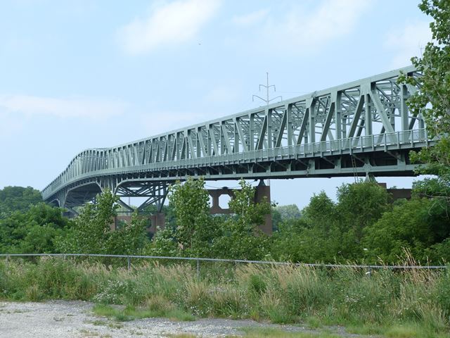
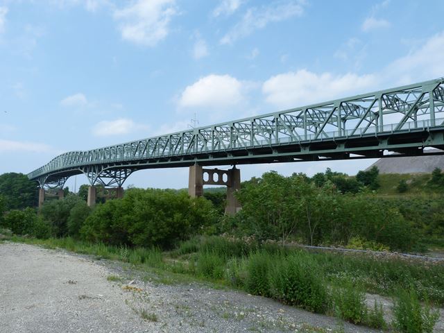
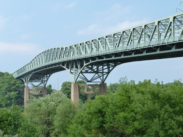
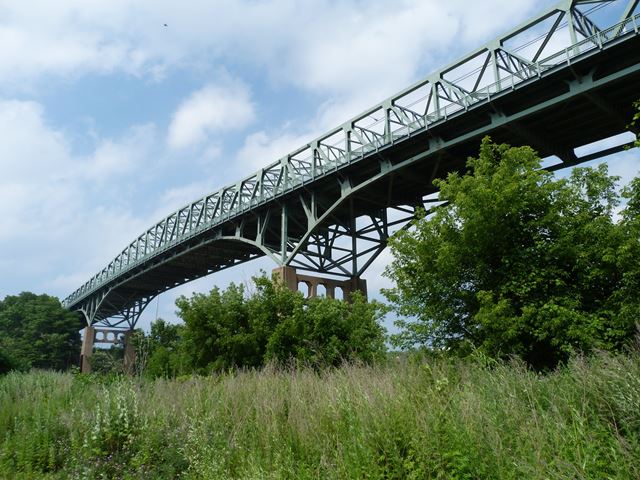
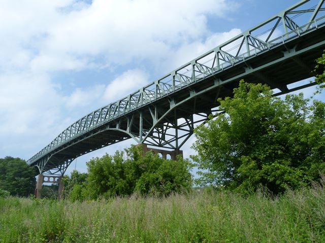
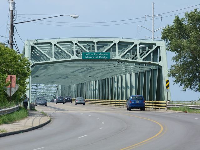
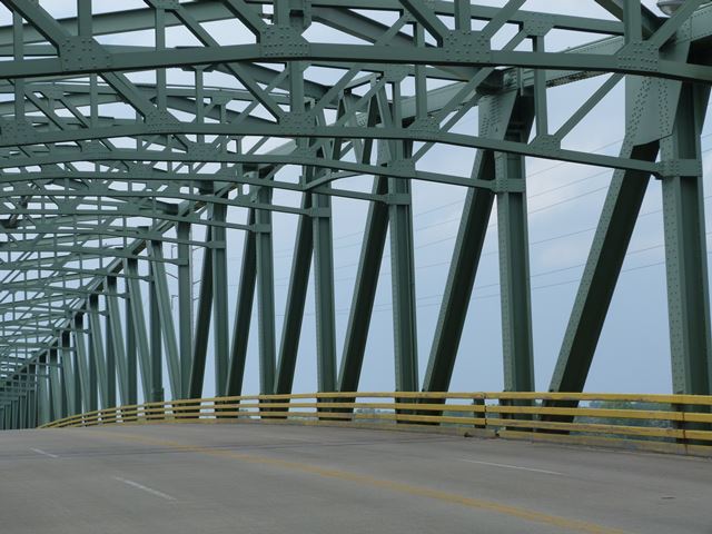
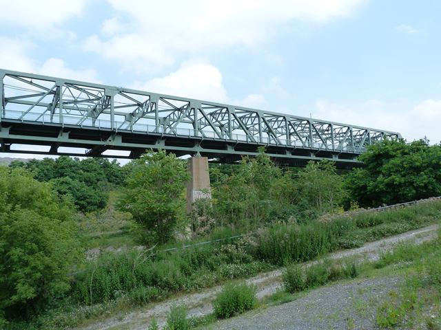
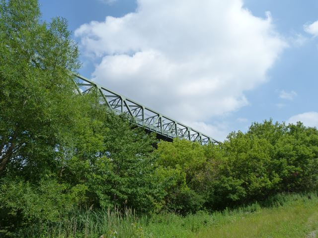
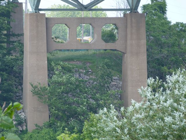
Views beside approach span from southwest quadrant.
![]()
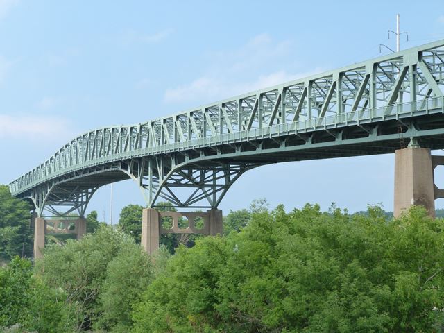
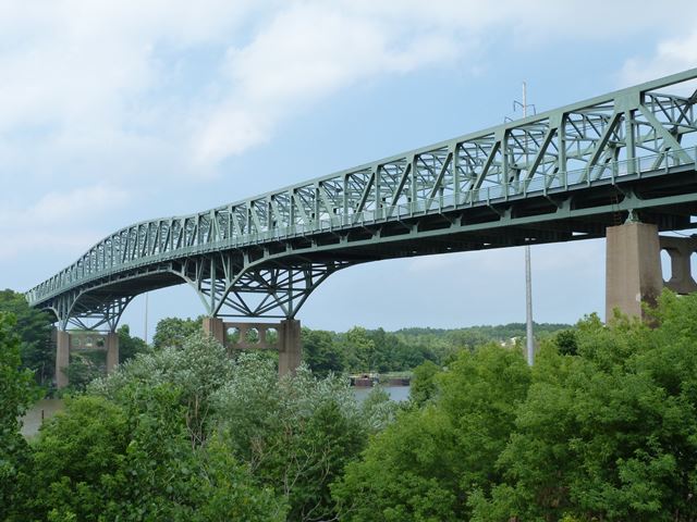
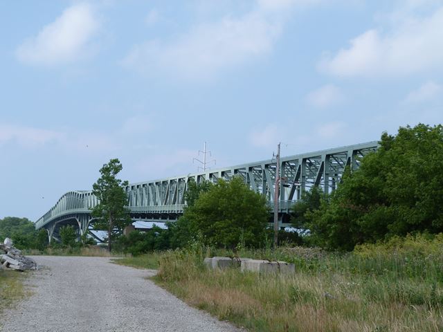
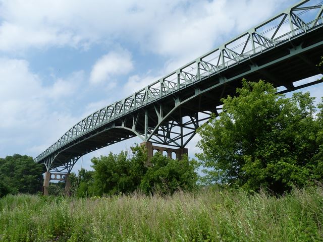
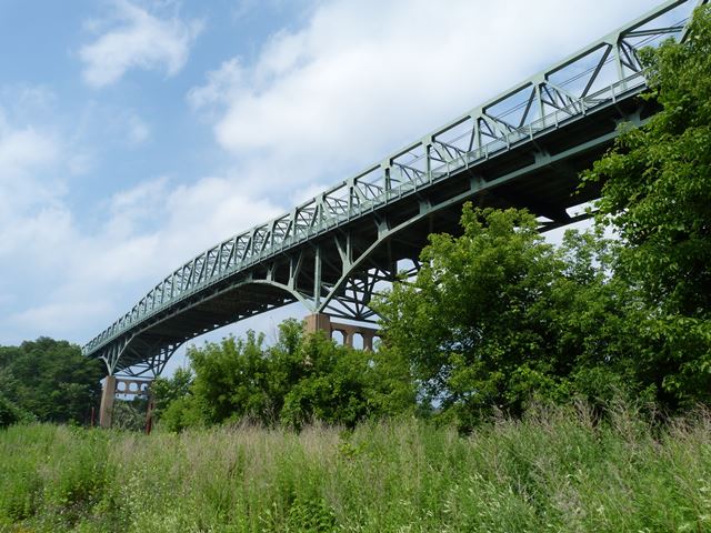
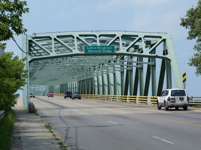
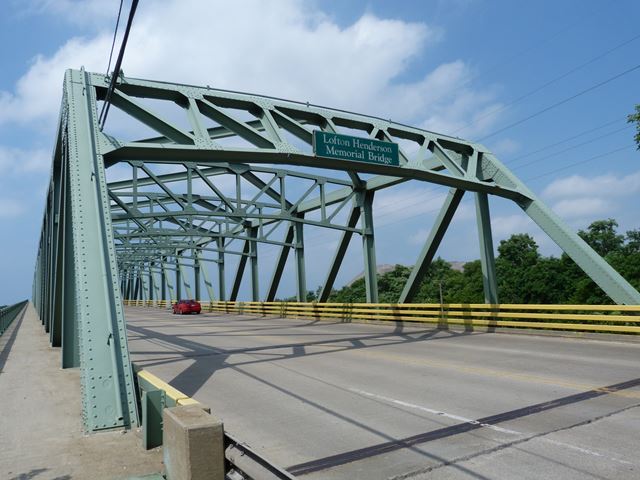
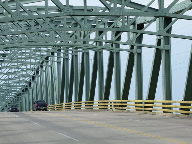
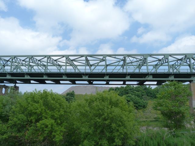
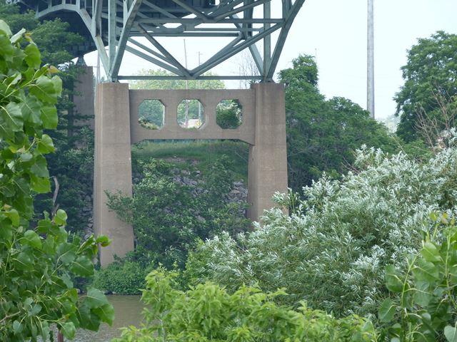
View beside bridge showing main span from southwest quadrant.
![]()
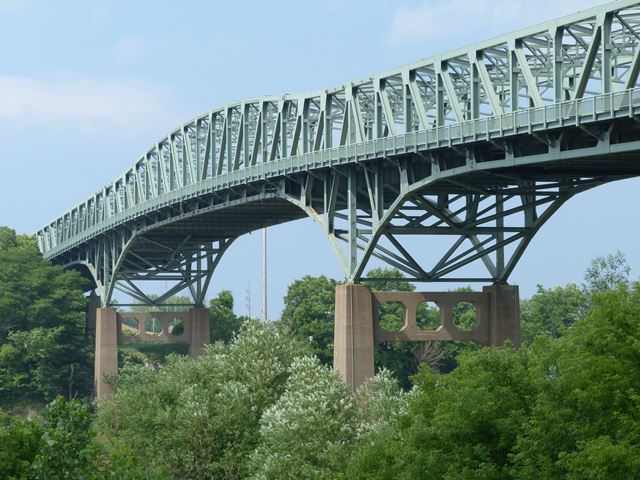
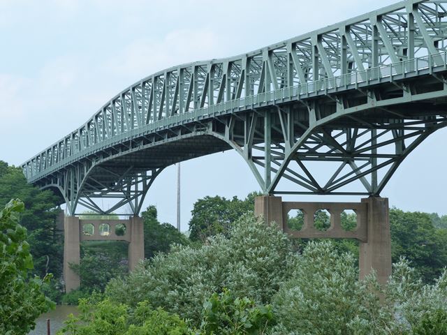
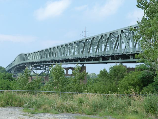
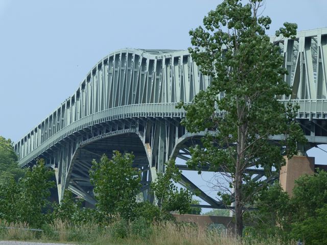
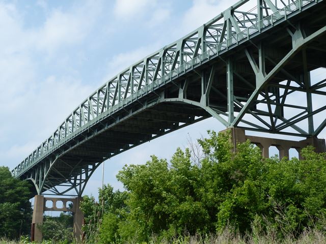
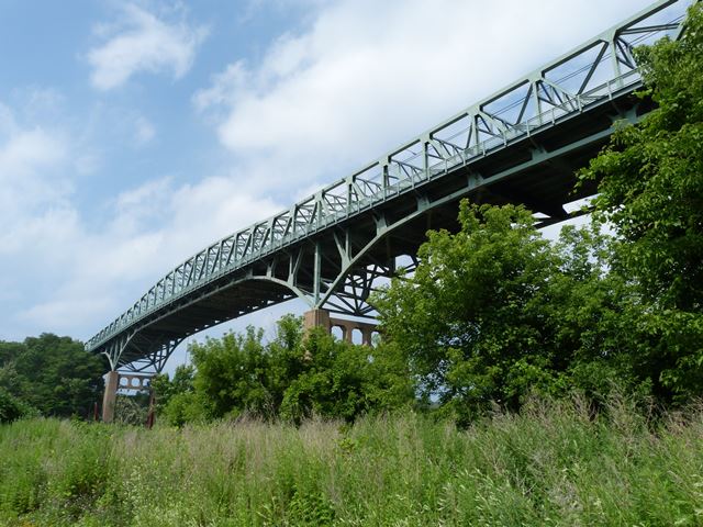
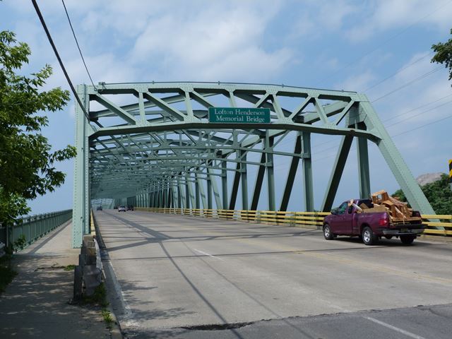
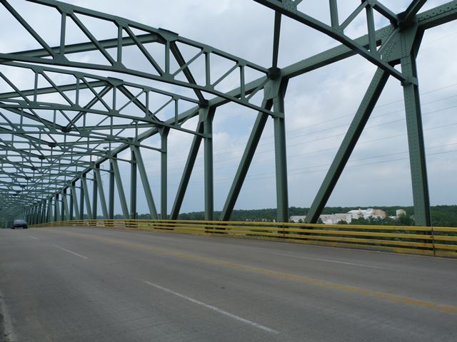
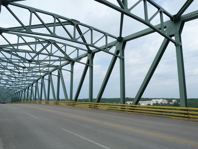
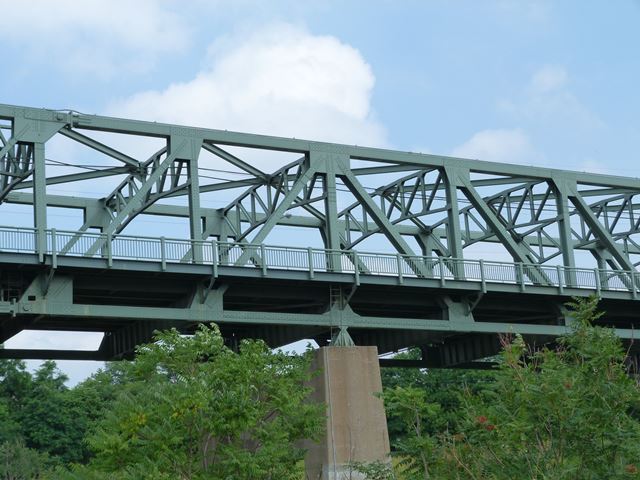
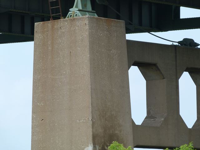
Views beside bridge near main channel span from southwest quadrant.
![]()
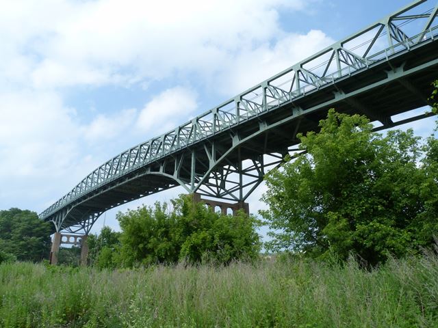
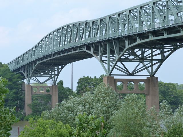
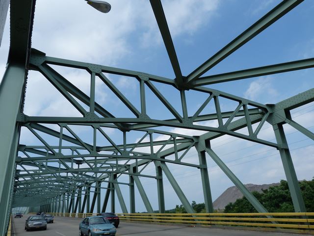
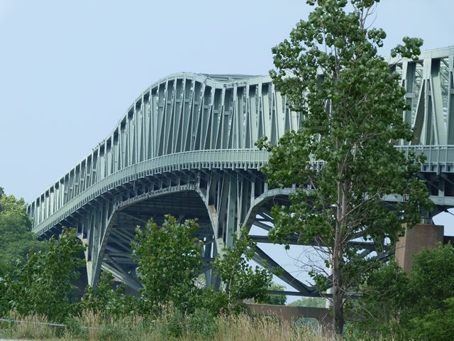
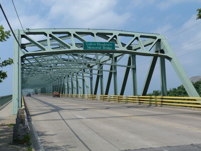
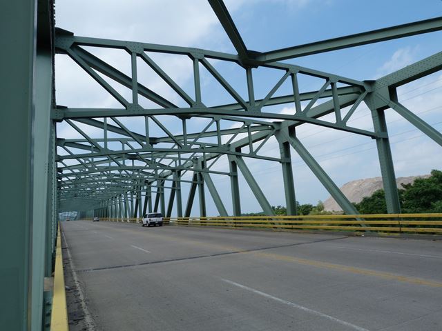
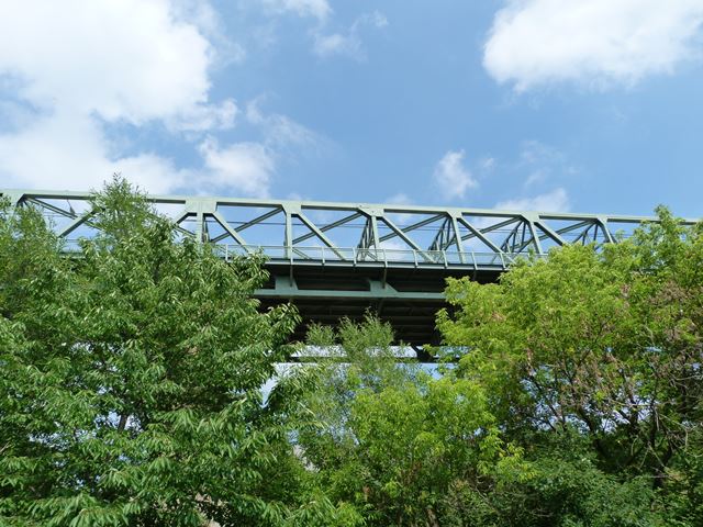
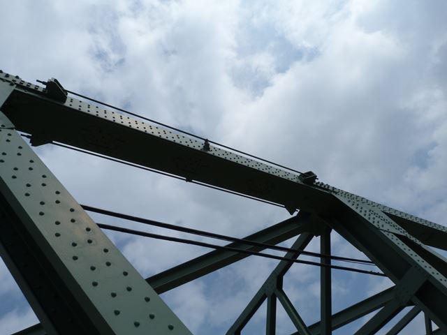
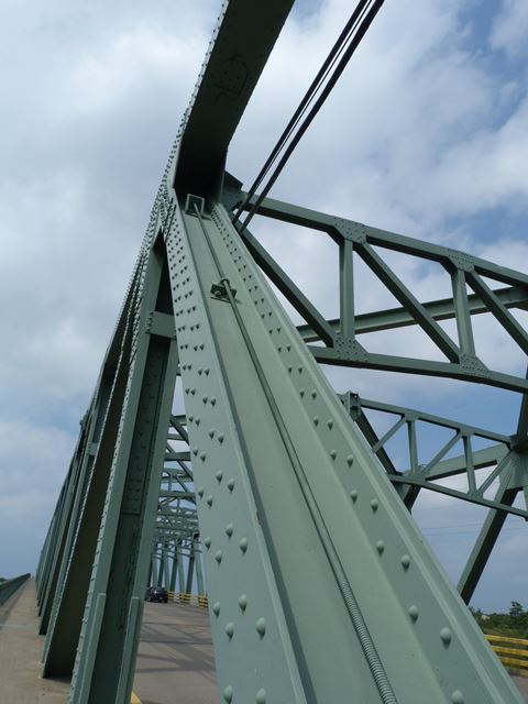
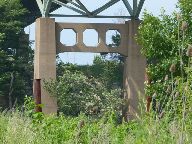
Looking up at main channel span from southwest quadrant.
![]()
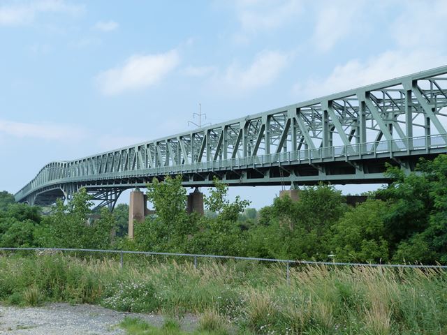
Views beside approaching roadway from southwest quadrant.
![]()
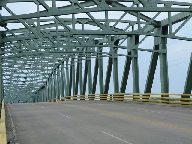
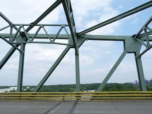
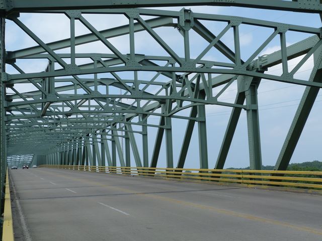
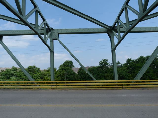
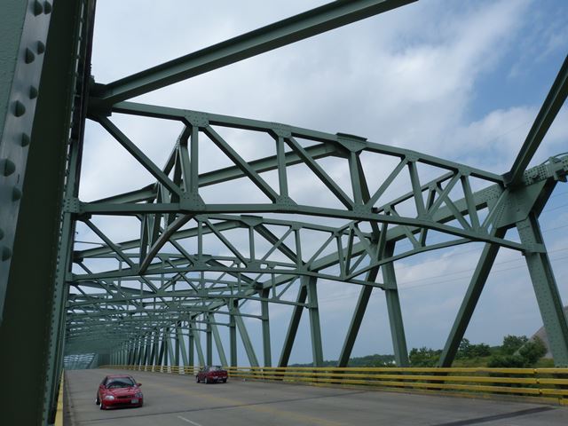
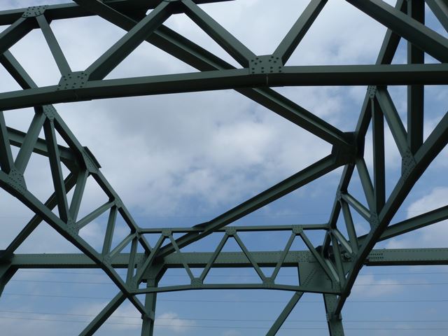
Views of the channel span truss web.
![]()
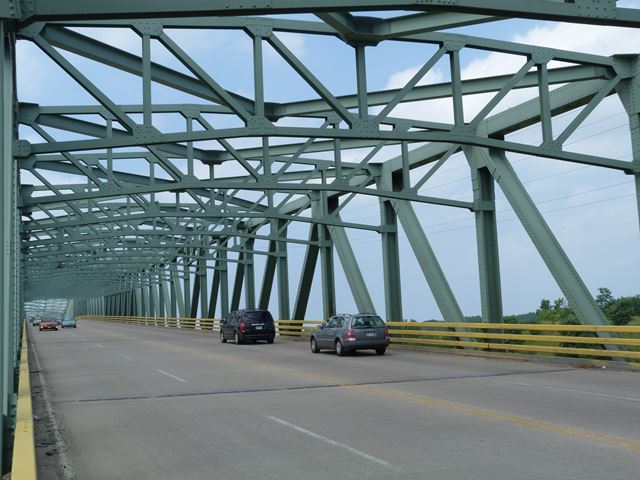
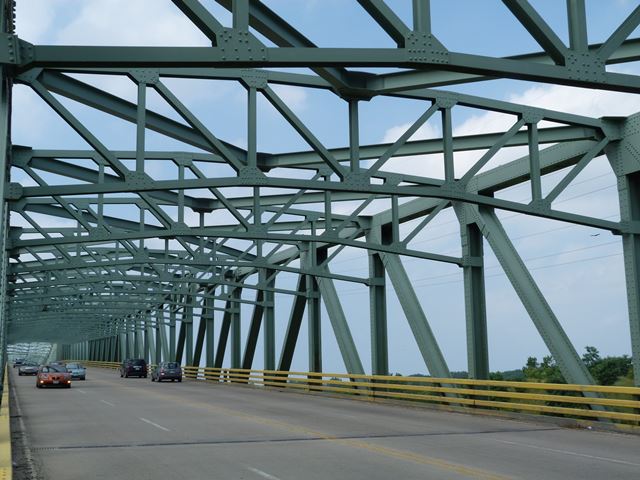
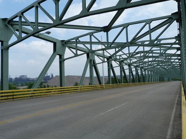
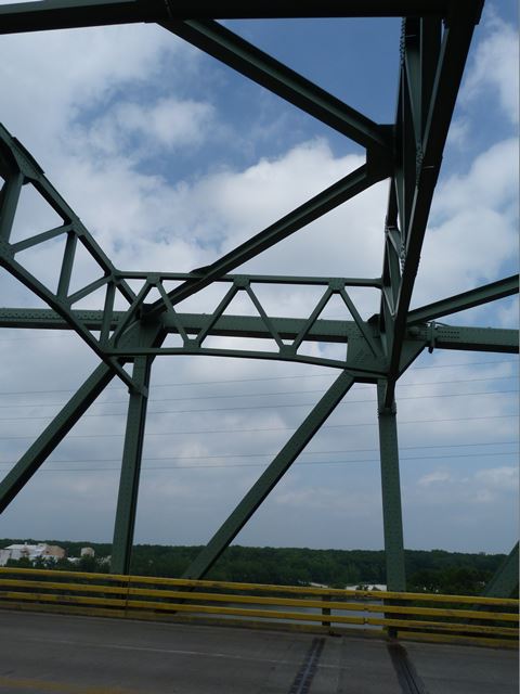
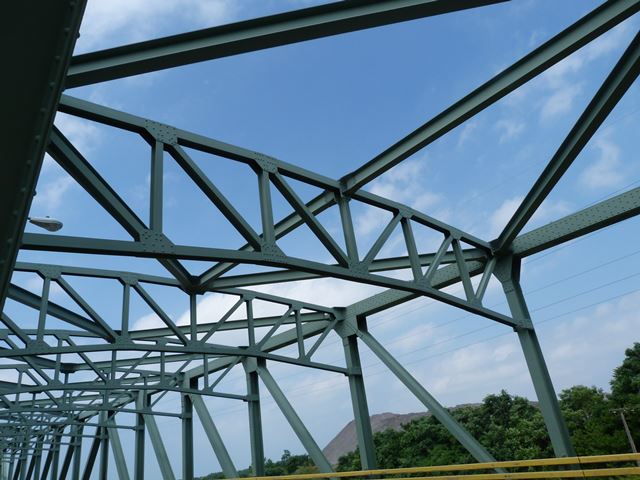
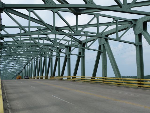
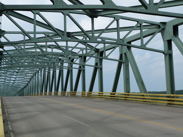
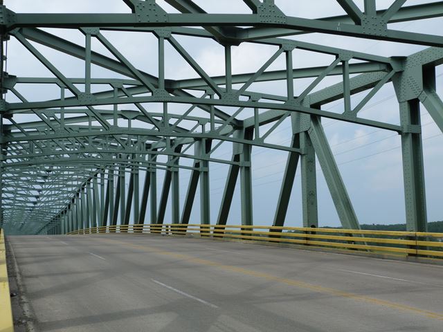
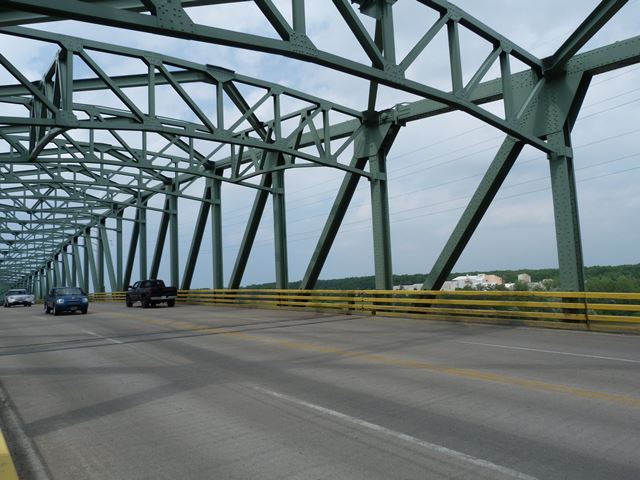
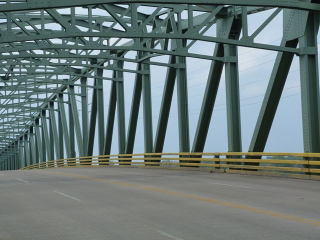
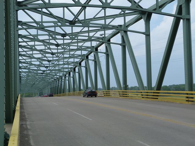
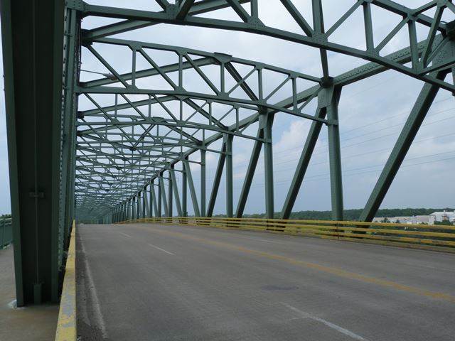
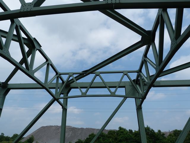
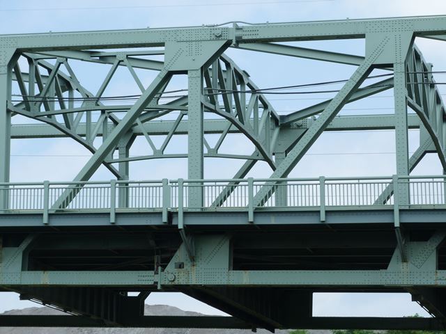
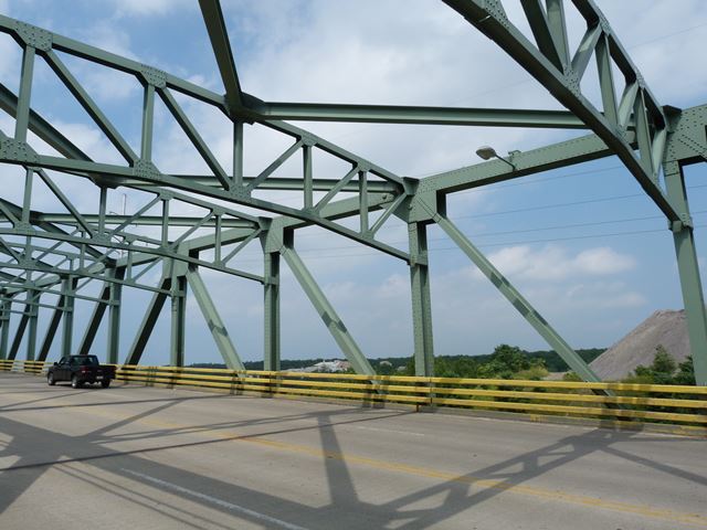
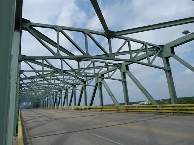
Approach spans truss web as viewed from on bridge.
![]()
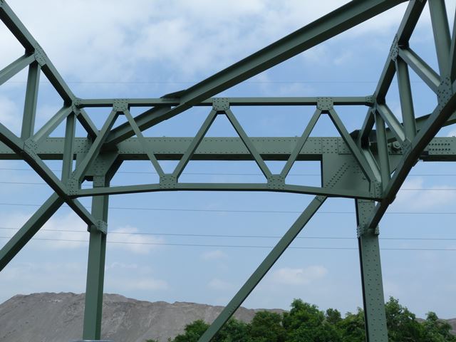
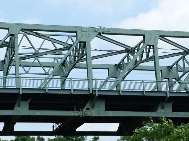
Approach spans truss web as viewed from beside bridge.
![]()
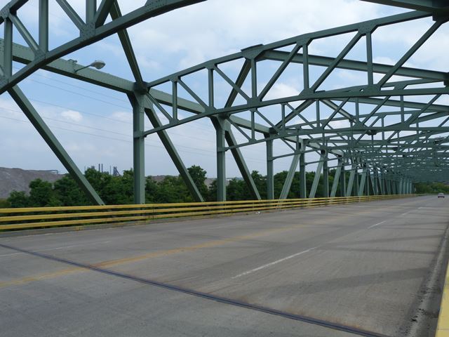
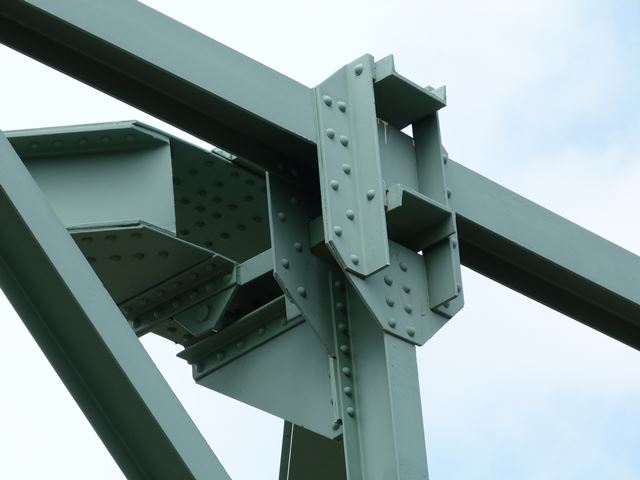
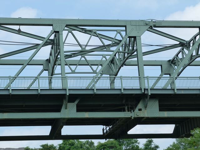
Approach spans truss panels.
![]()
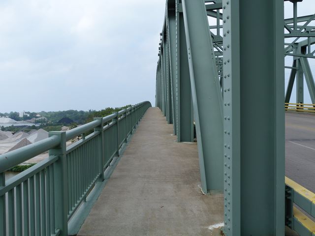
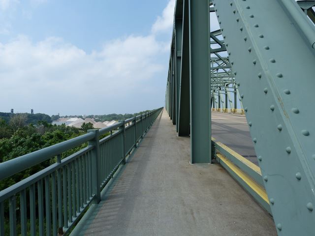
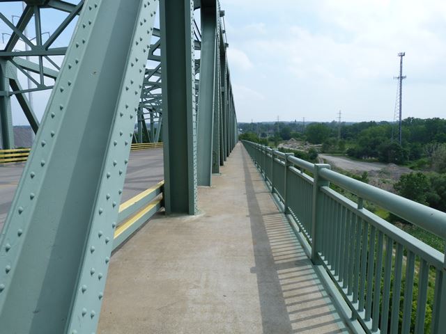
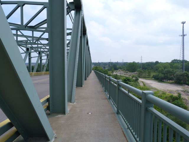
Views on west sidewalk.
![]()
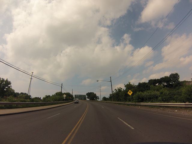
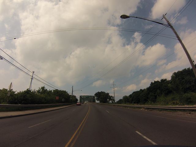
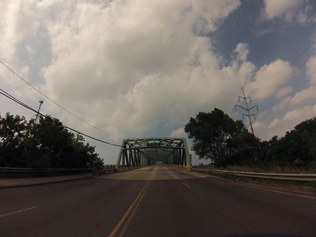
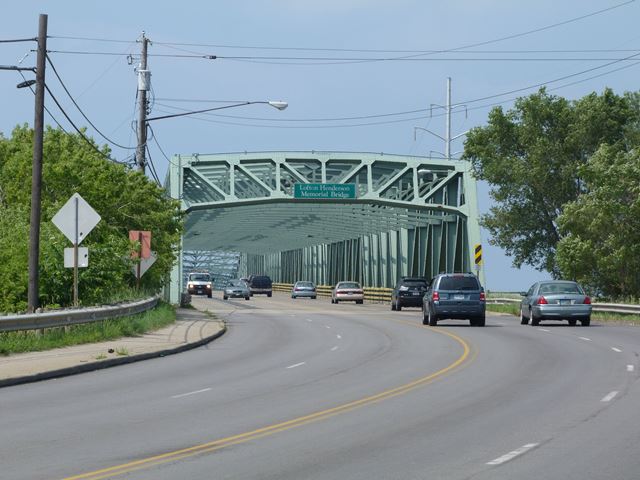
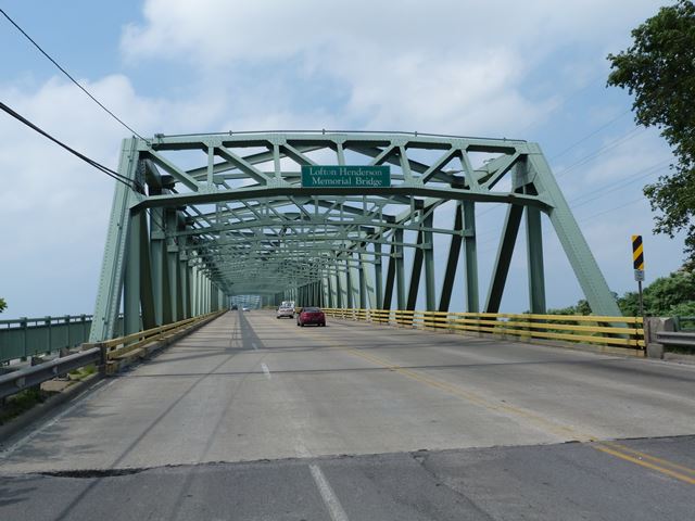
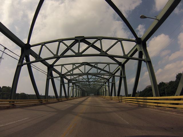
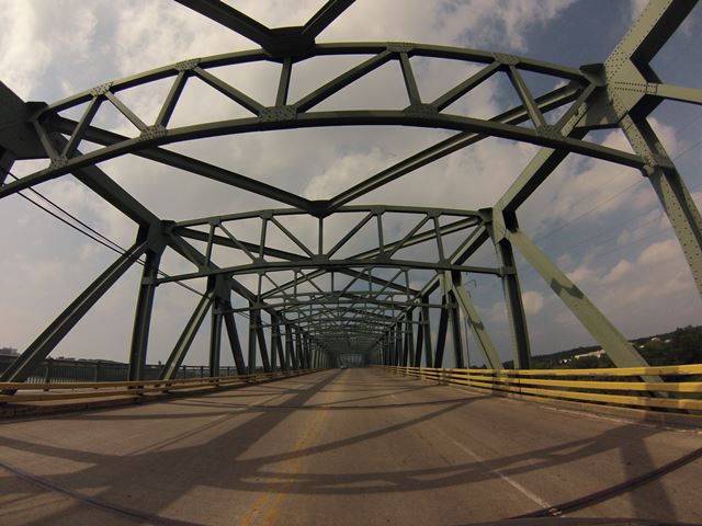
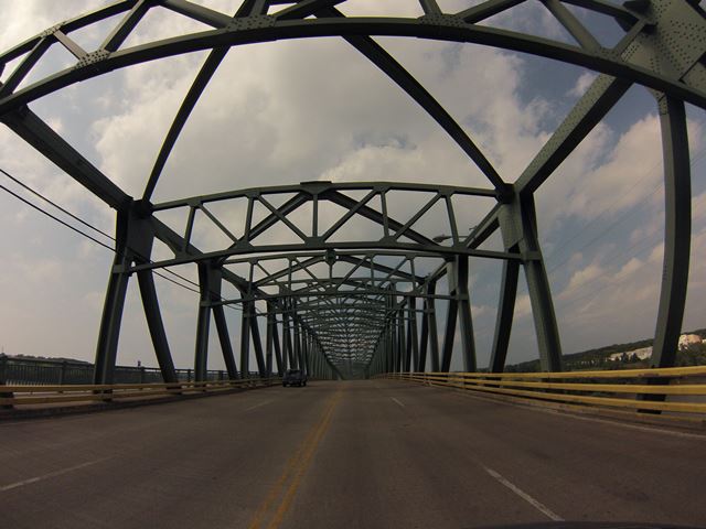
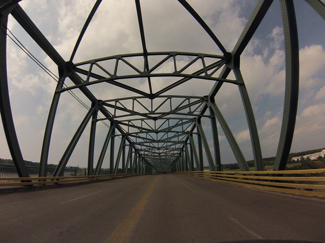
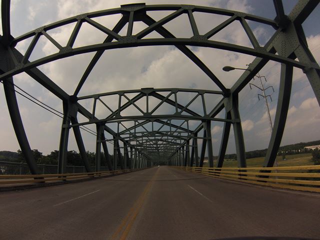
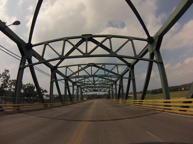
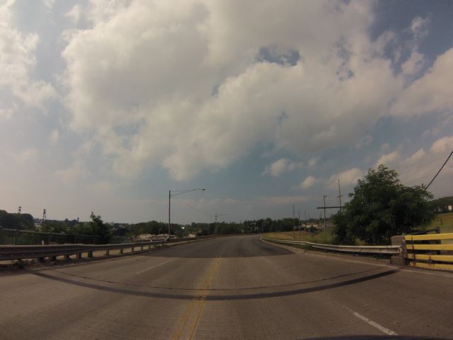
GoPro CarCam photos, northbound crossing. Approaching bridge.
![]()
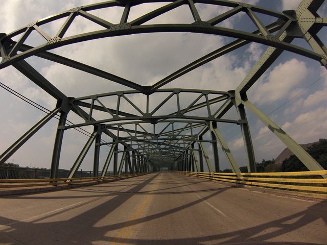
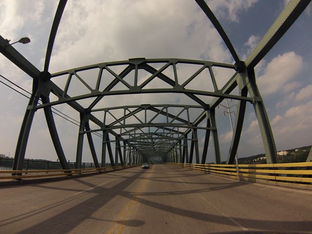
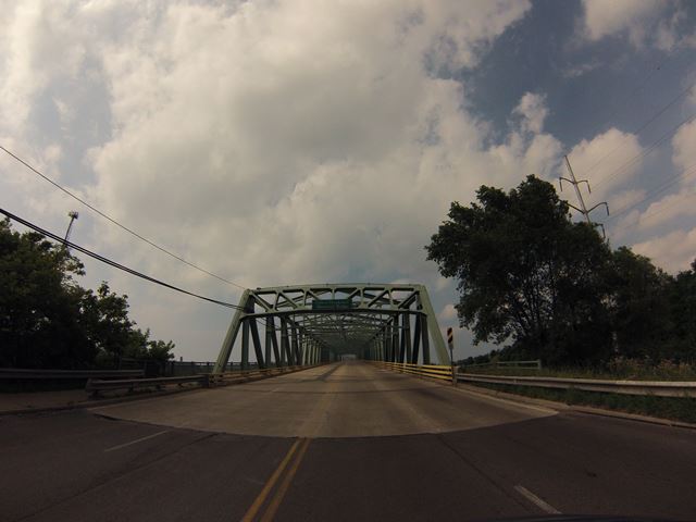
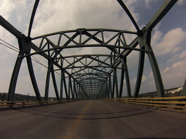
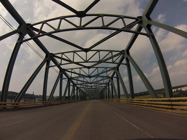
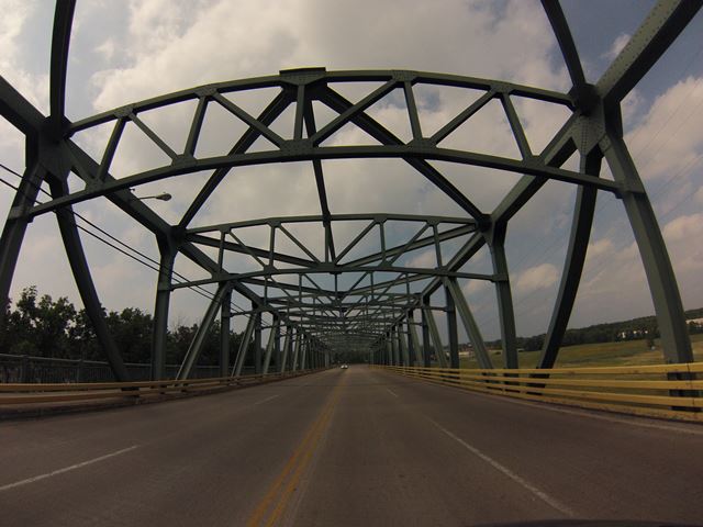
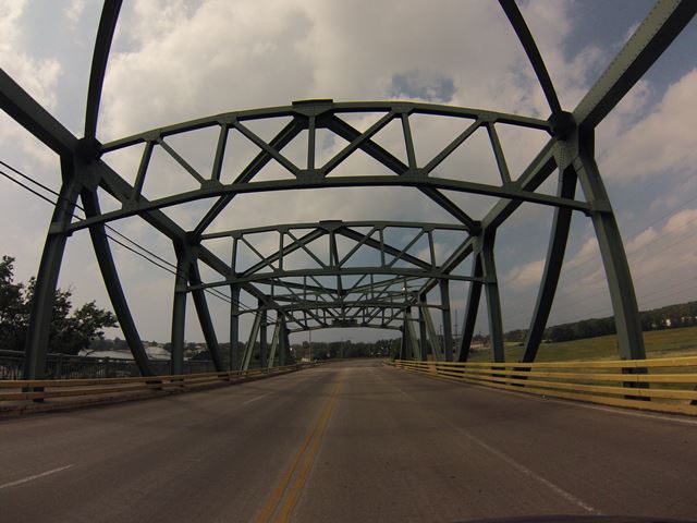
GoPro CarCam photos, northbound crossing. Southern approach spans.
![]()
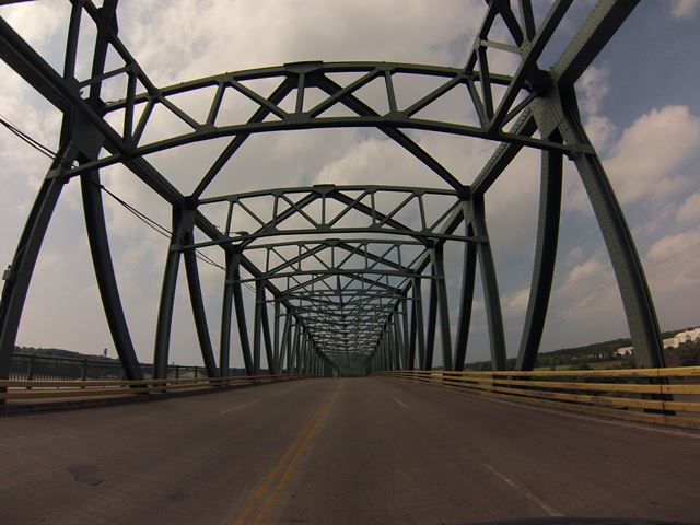
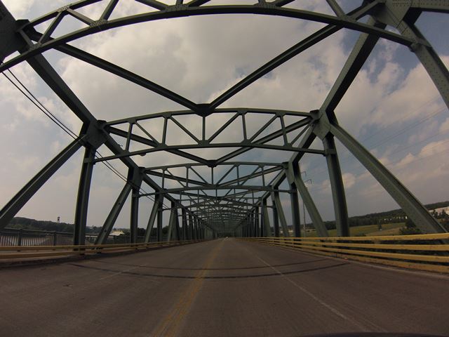
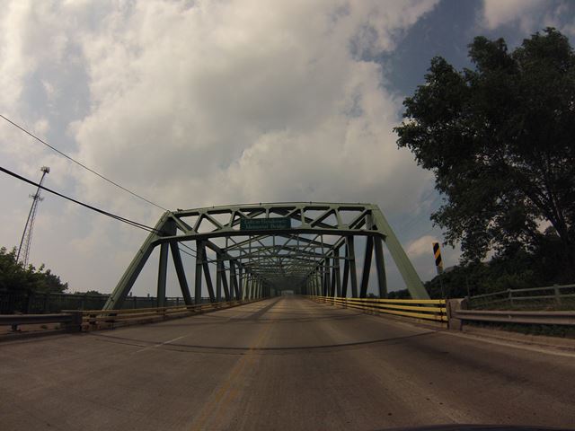
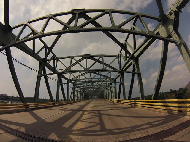
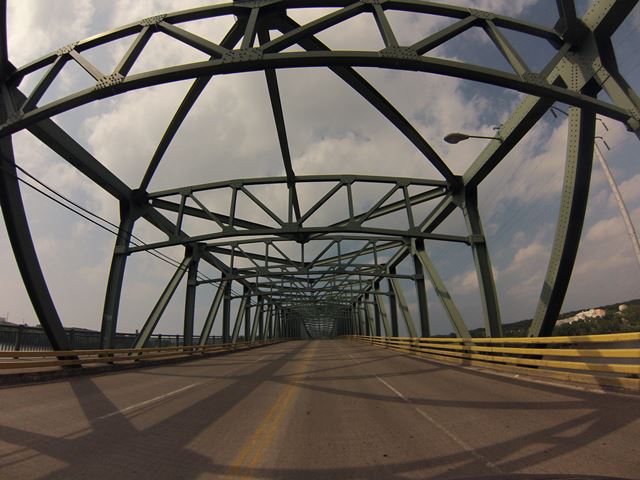
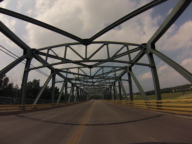
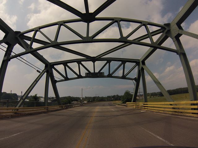
GoPro CarCam photos, northbound crossing. Vicinity of the channel span.
![]()
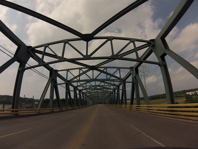
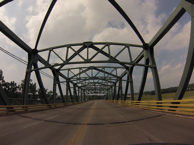
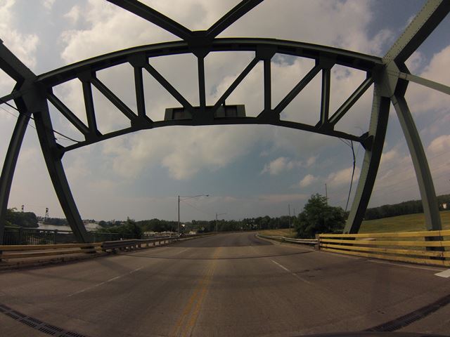
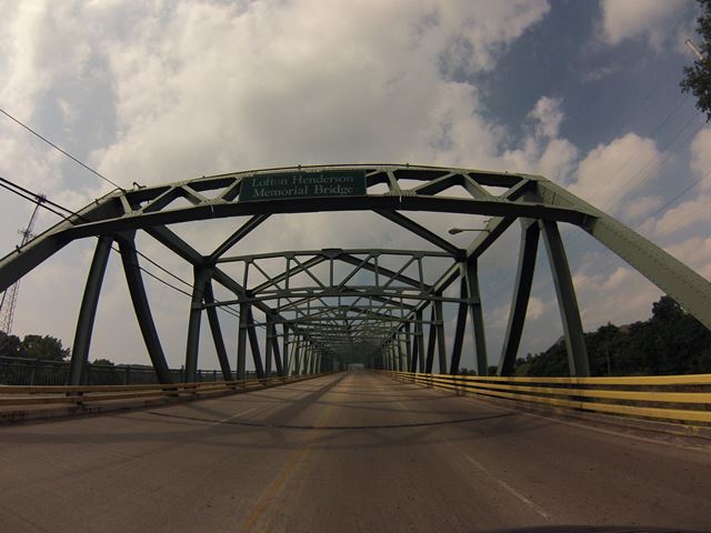
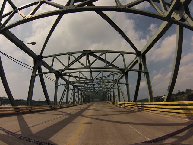
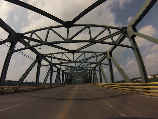
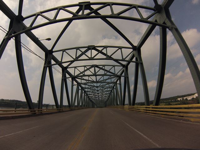
GoPro CarCam photos, northbound crossing. Northern approach spans.
![]()
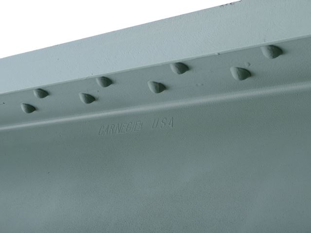
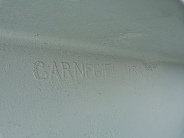
Carnegie brand.
![]()
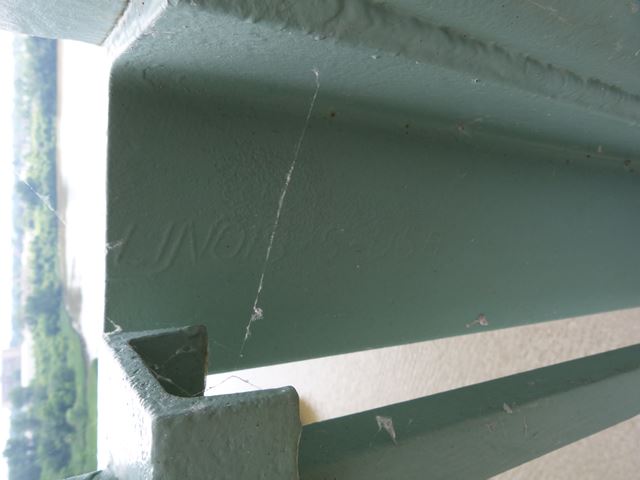
Illinois brand.
![]()
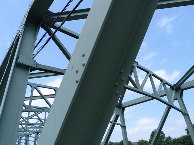
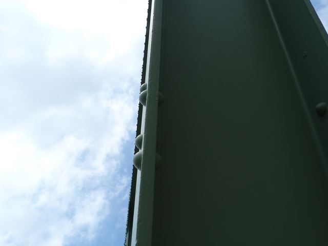
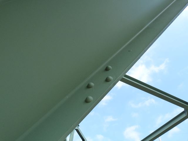
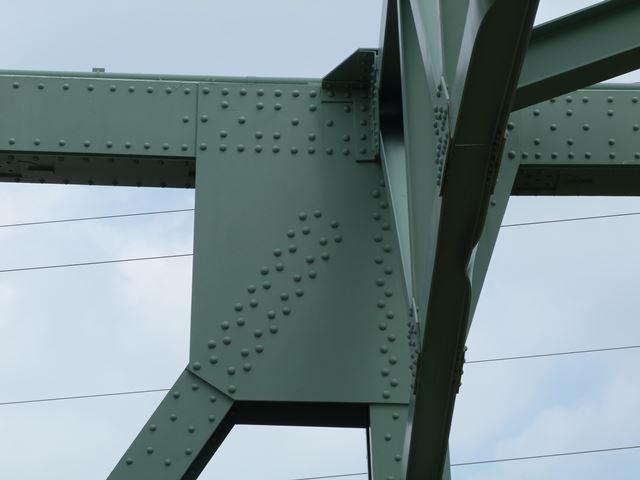
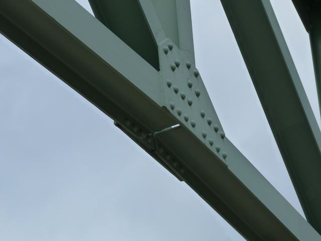
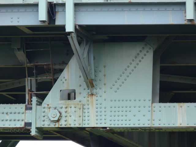
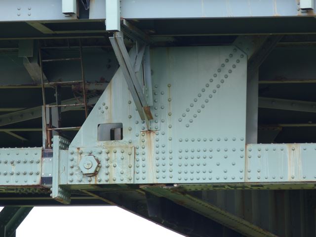
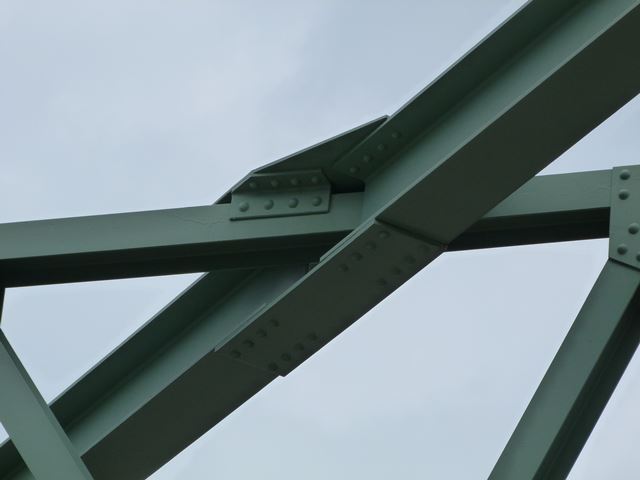
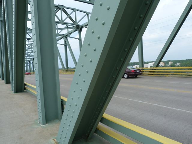
These rivets on a diagonal look like they aren't doing anything!
![]()
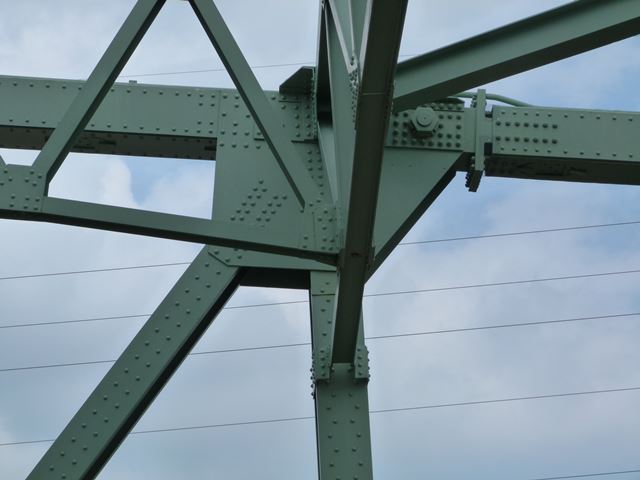
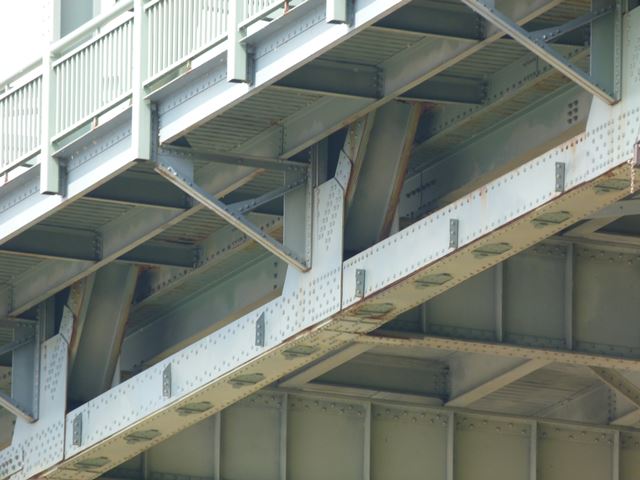
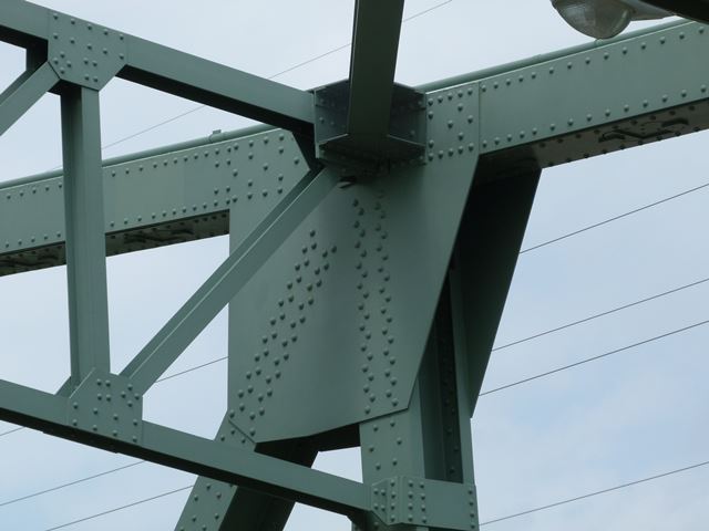
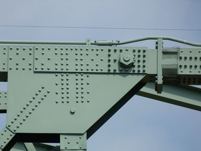
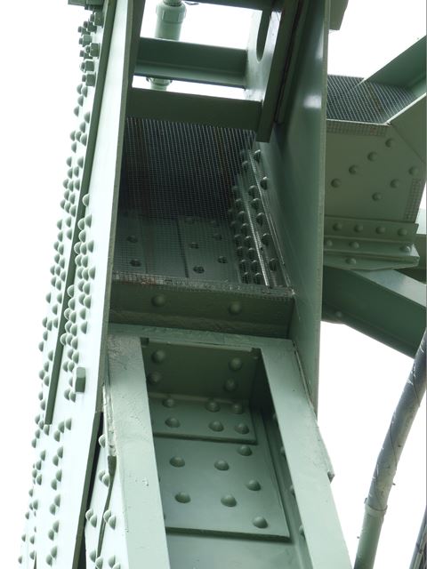
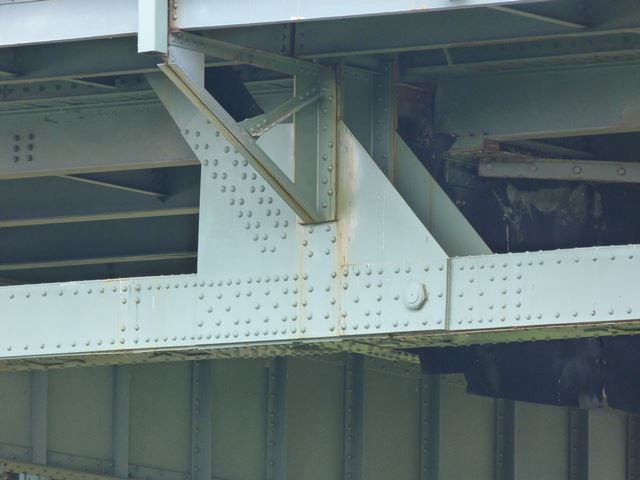
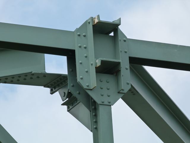
Overhead bracing at the end of the approach suspended span.
![]()
Detail of overhead bracing at the end of the approach suspended span.
![]()
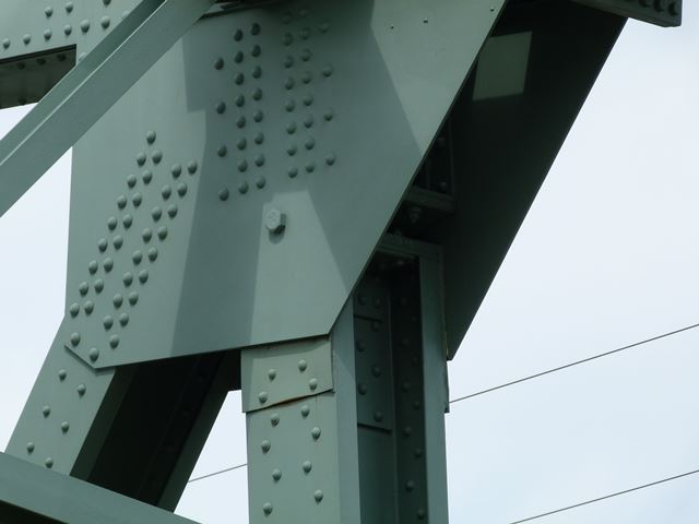
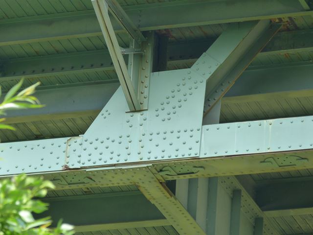
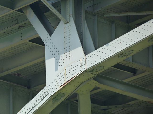
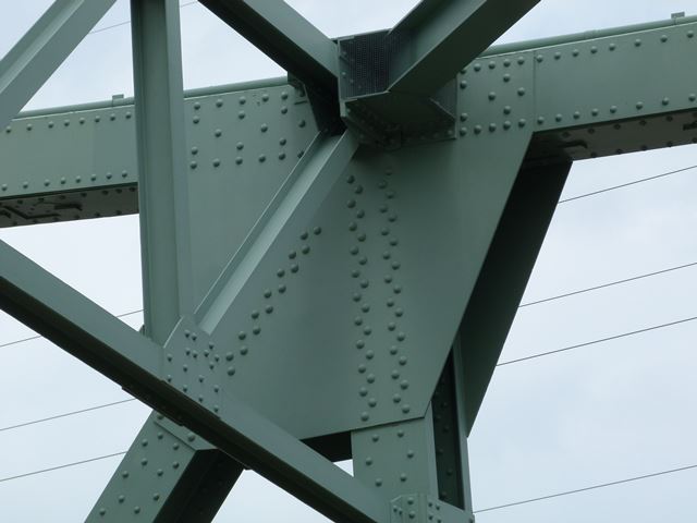
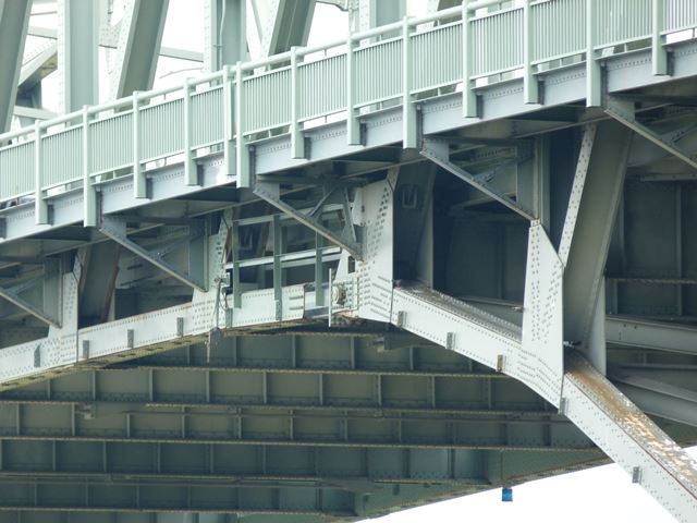
Pin and hanger system at end of approach suspended span.
![]()
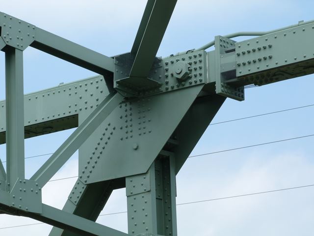
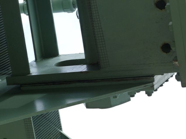
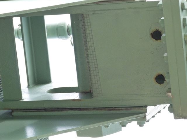
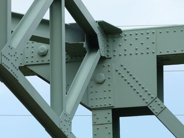
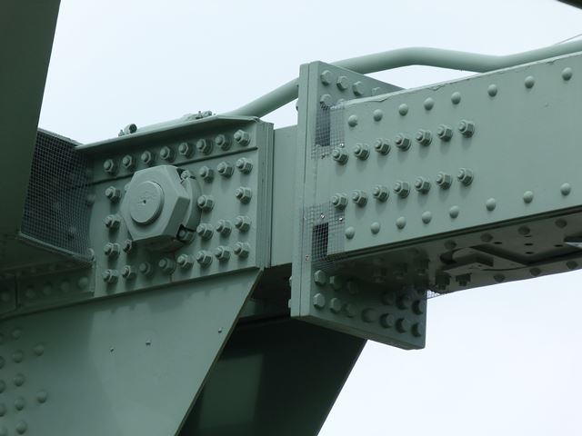
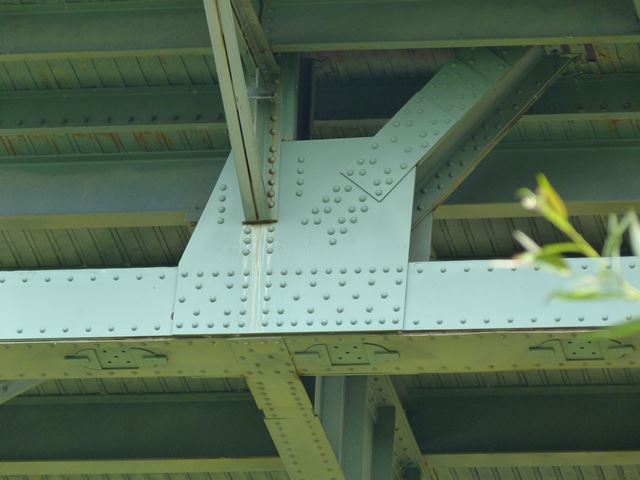
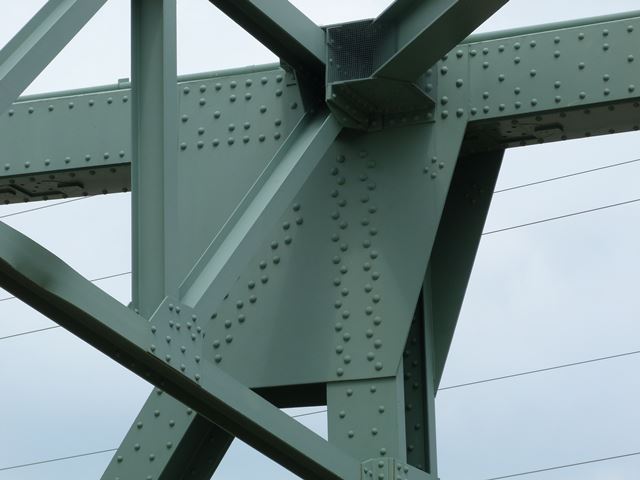
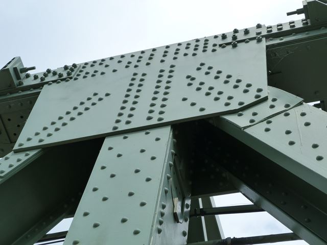
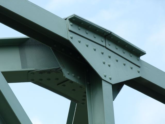
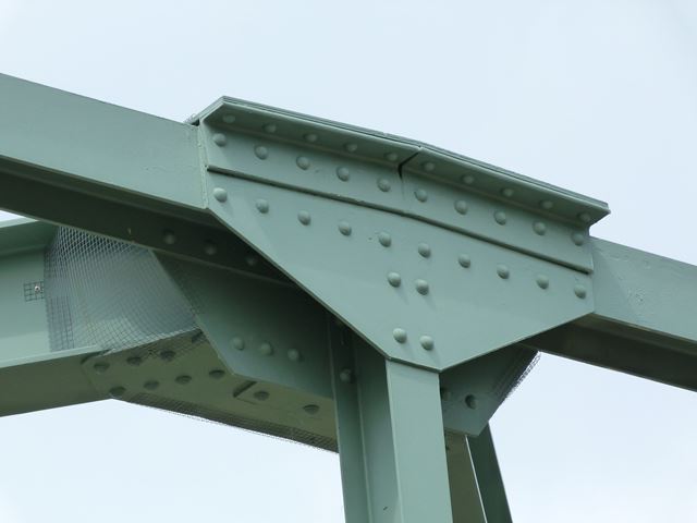
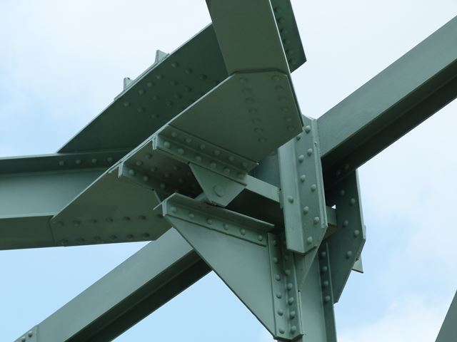
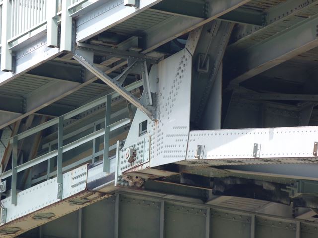
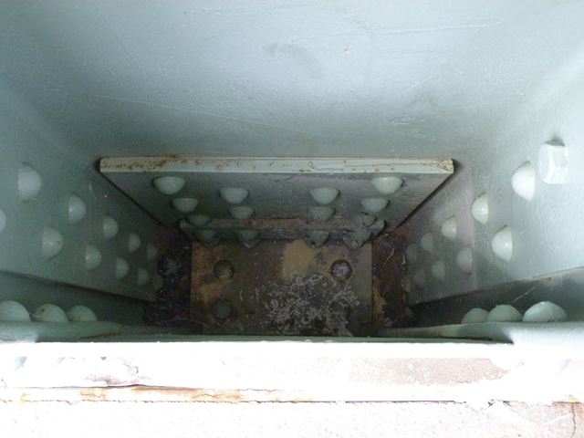
Top chord pin connection at end of approach suspended span.
![]()
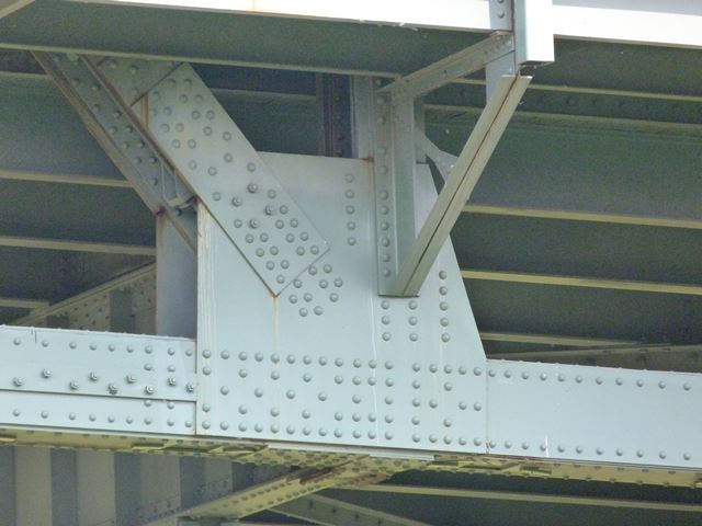
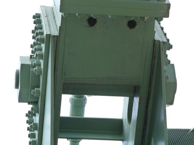
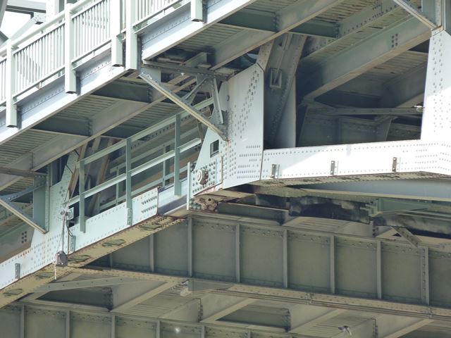
Top chord pin connection at the other end of the approach suspended span.
![]()
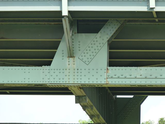
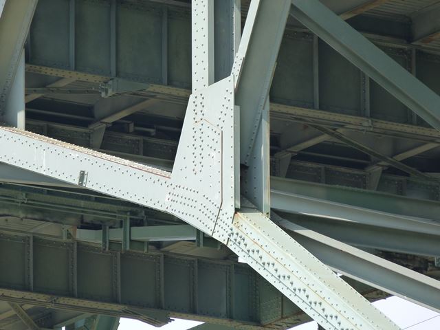
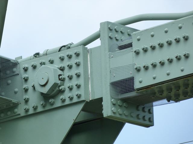
Bottom chord pin connection at end of approach suspended span.
![]()
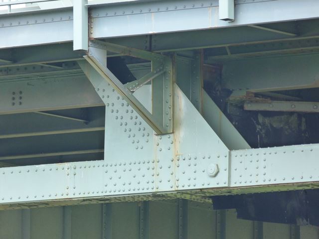
Bottom chord pin connection at the other end of approach suspended span.
![]()
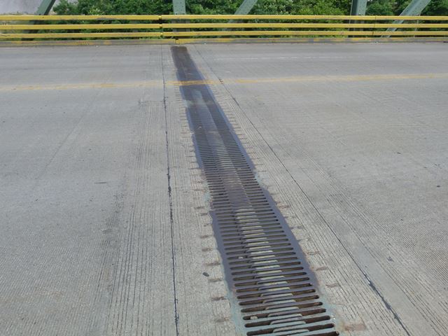
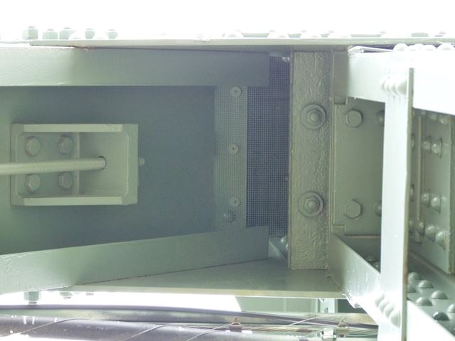
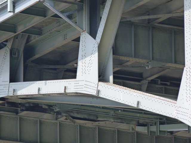
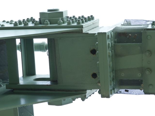
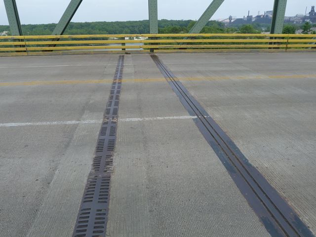
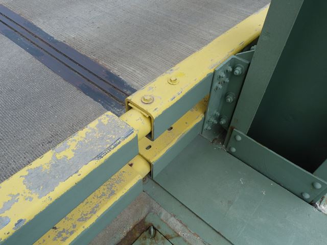
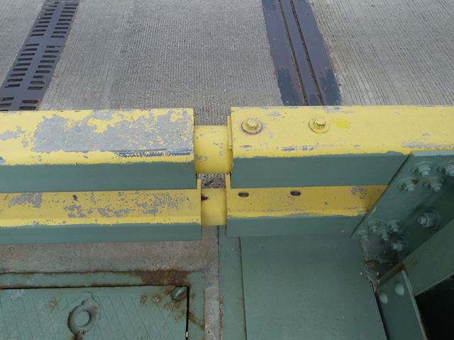
Expansion joint for approach suspended span.
![]()
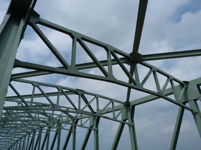
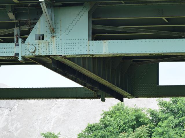
View of truss web looking toward the northern approach cantilever arm.
![]()
Truss panels at end of main (channel) suspended span.
![]()
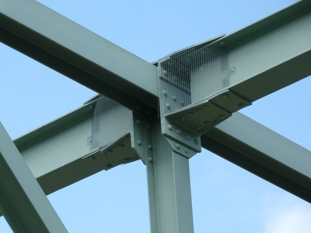
Overhead bracing connection at end of main (channel) suspended span.
![]()
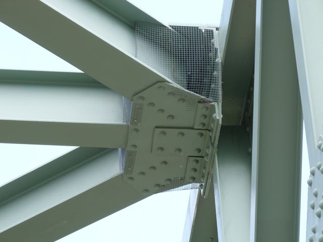
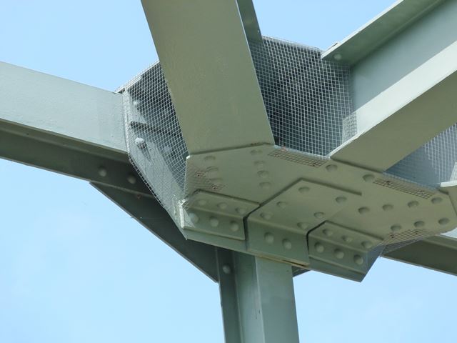
Top chord pin connections at end of main (channel) suspended span.
![]()
Bottom chord pin connections at end of main (channel) suspended span.
![]()
Expansion joints and expansion gaps at end of main (channel) suspended span.
![]()
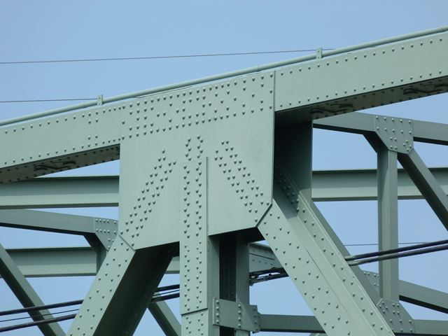
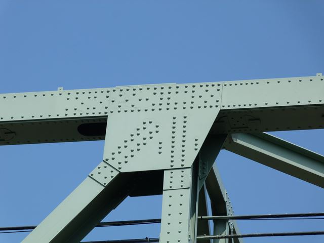
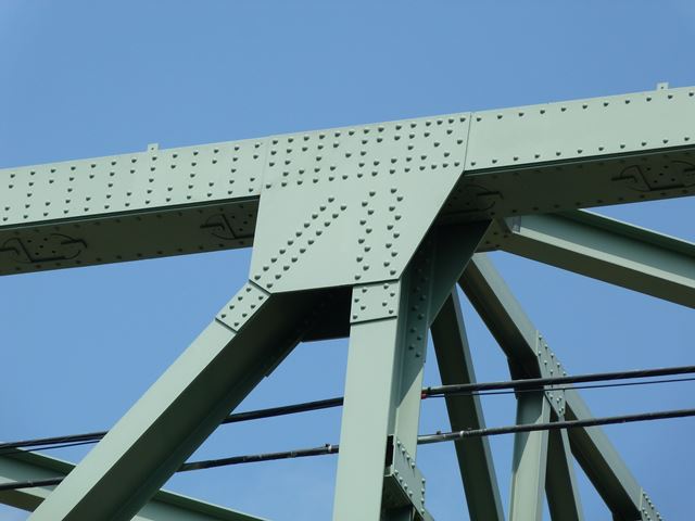
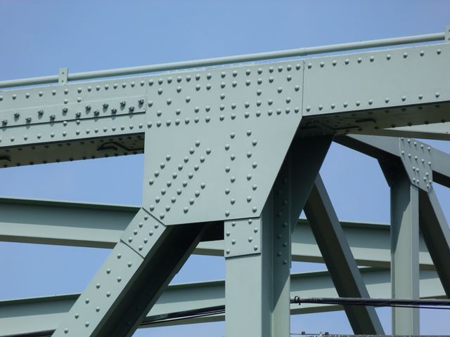
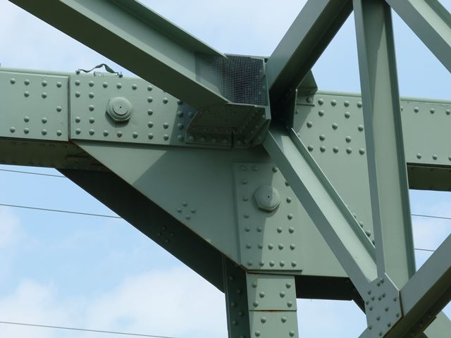
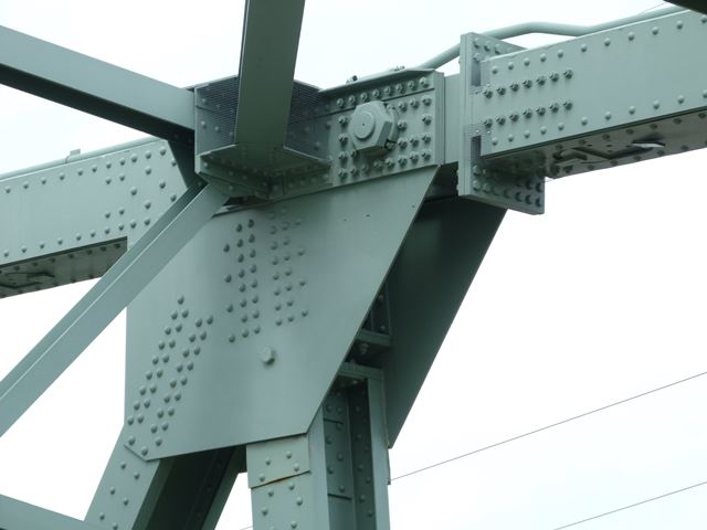
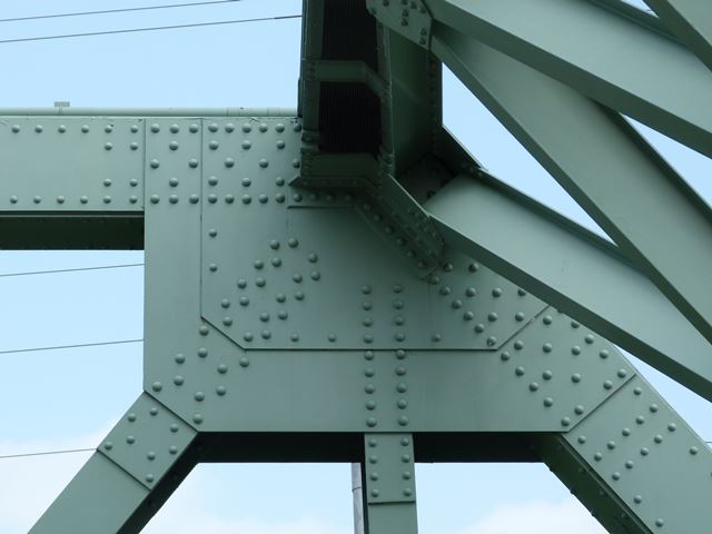
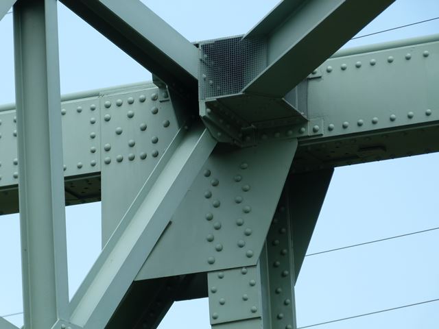
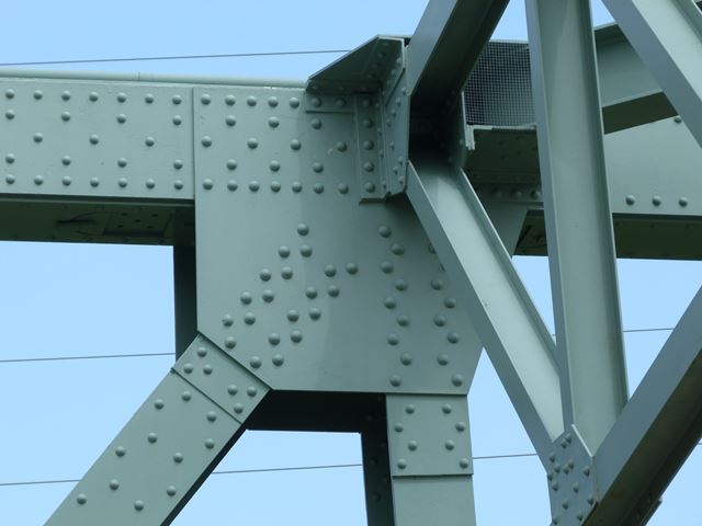
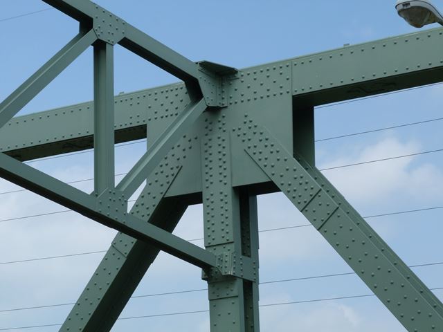
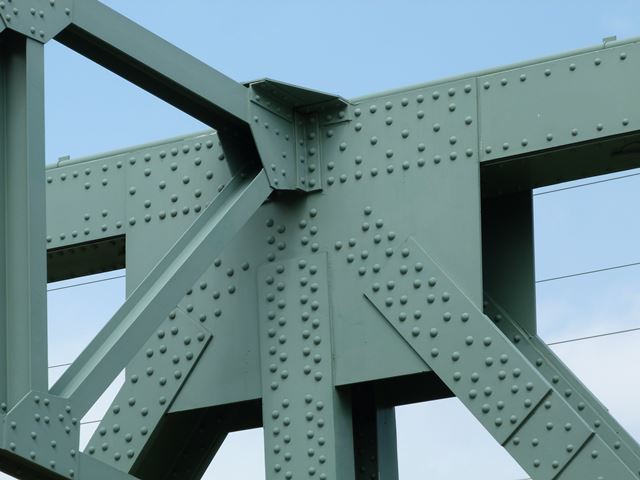
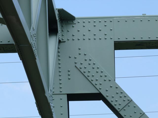
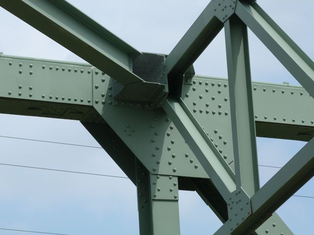
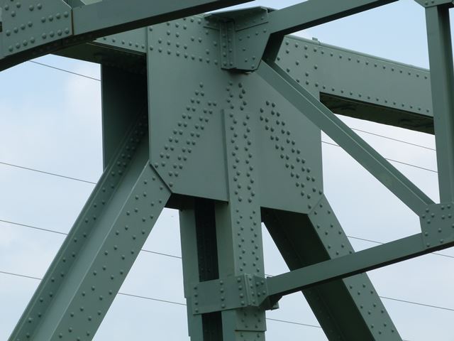
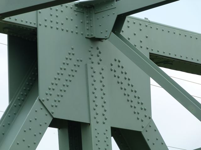
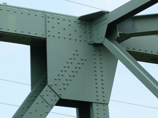
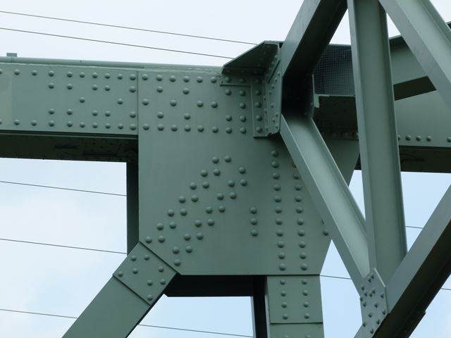
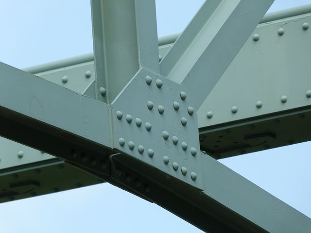
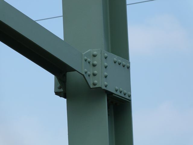
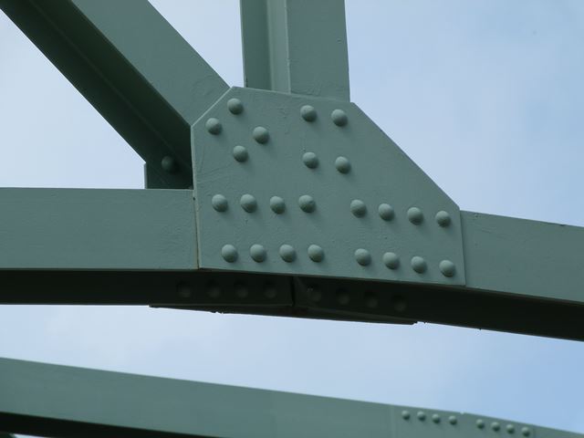
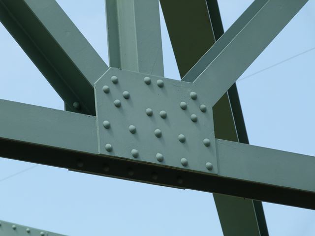
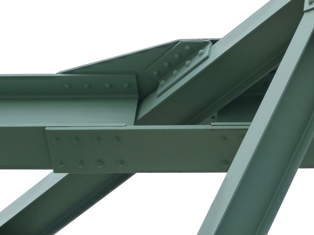
Top chord connections as viewed from beside bridge.
![]()
Bottom chord connections as viewed from beside bridge.
![]()
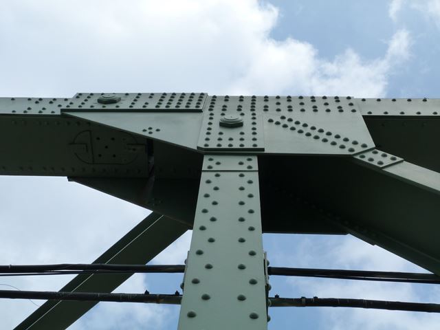
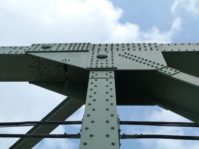
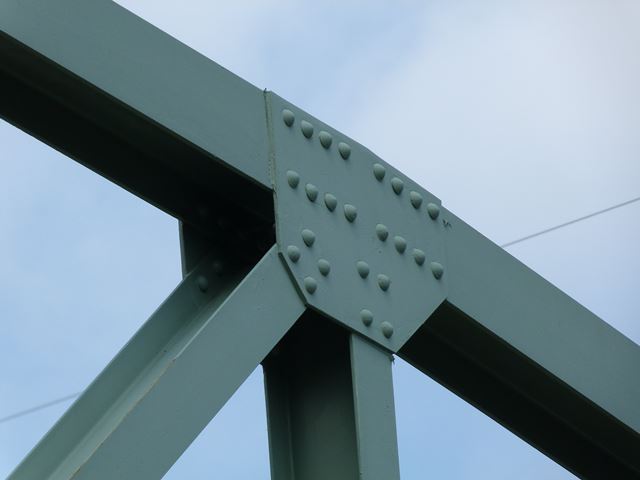
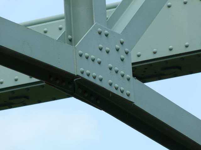
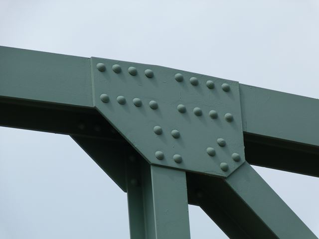
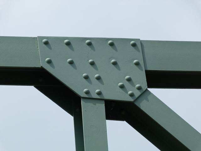
Top chord connections for approach trusses as viewed from on bridge.
![]()
Bottom chord connections for approach trusses as viewed from on bridge.
![]()
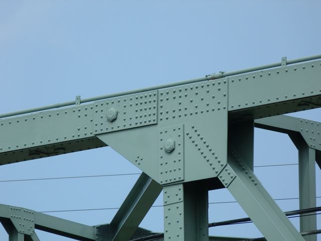
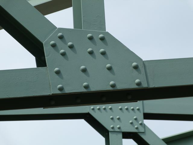
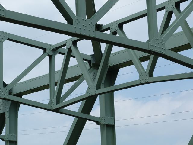
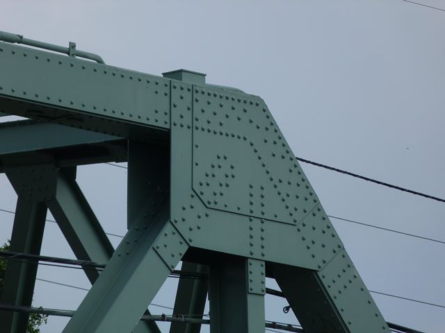
Top chord connections on and around the polygonal (arched) portion of the truss as viewed from on bridge.
![]()
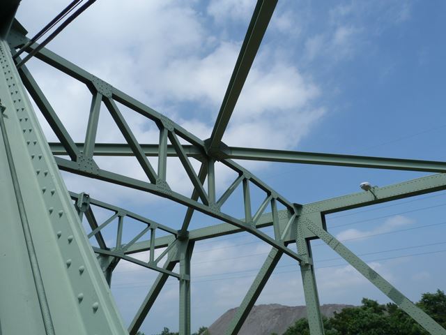
Sway bracing.
![]()
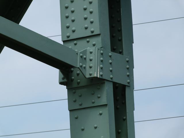
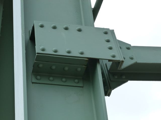
Lateral and sway bracing connections.
![]()
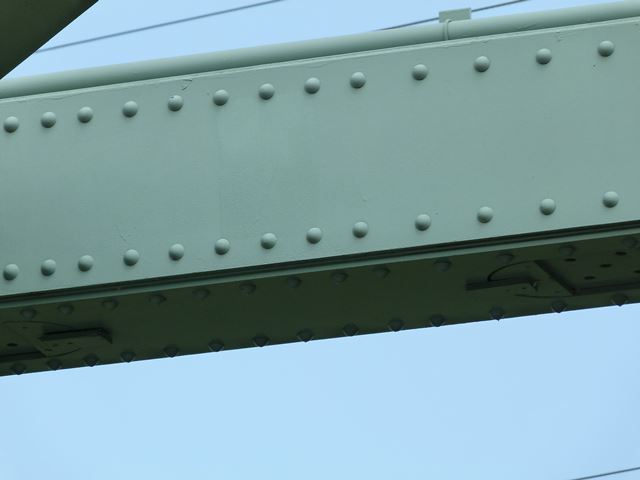
Top chord.
![]()
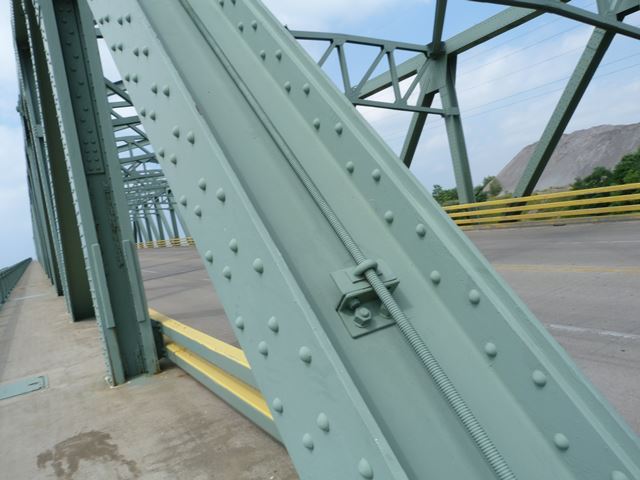
Rods added to top chord.
![]()
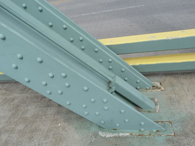
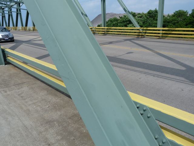
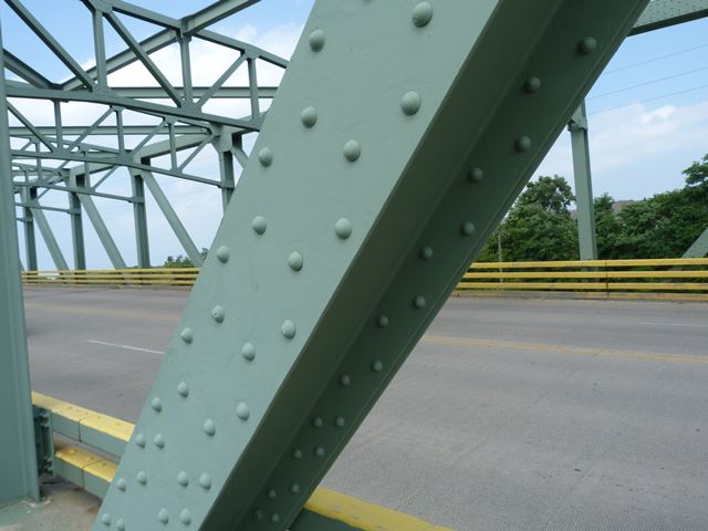
End post.
![]()
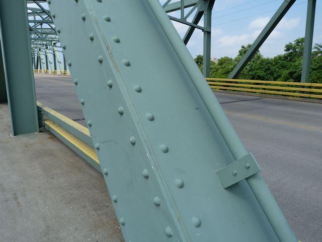
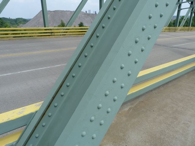
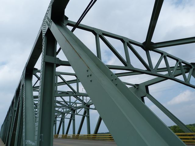
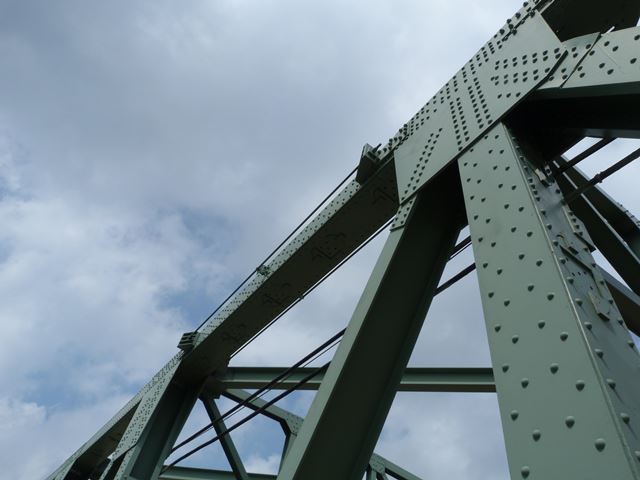
Diagonal members.
![]()
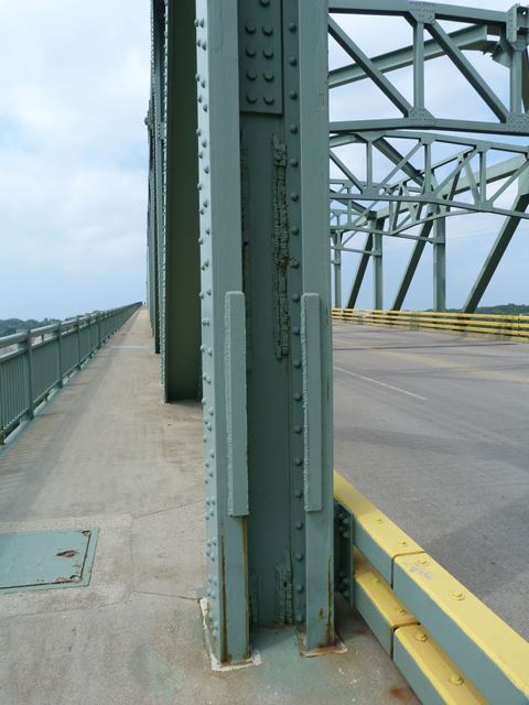
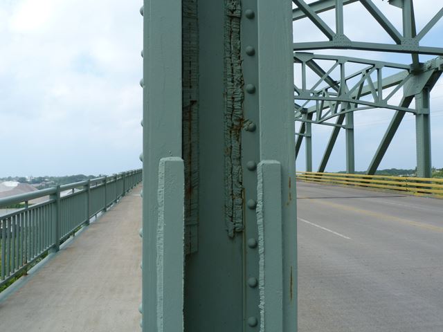
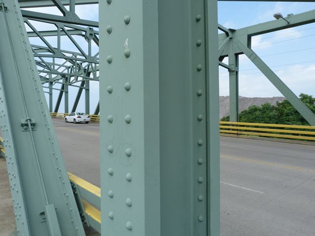
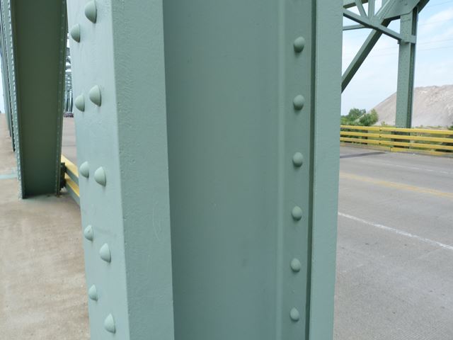
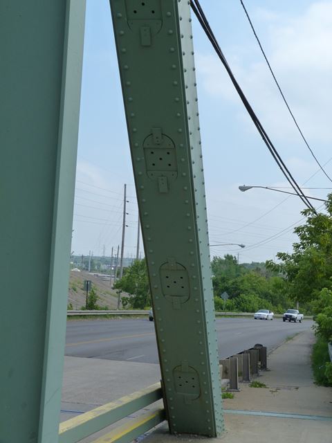
Vertical members.
![]()
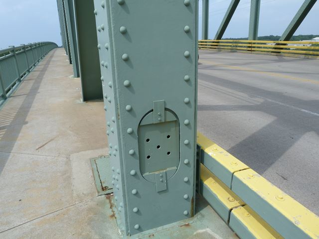
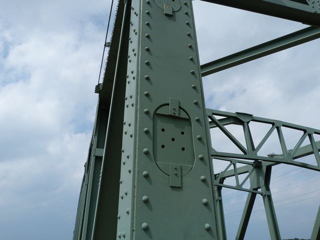
Vertical members with original hand holes covered up with bolted plate.
![]()
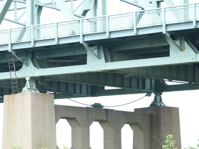
Cable added under approach spans at pier.
![]()
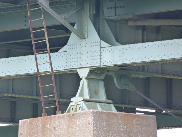
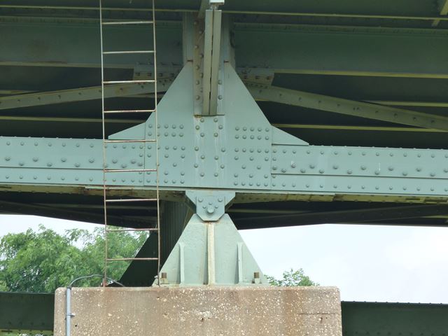
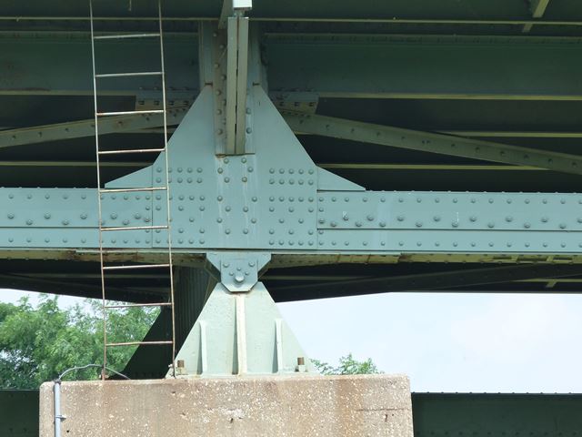
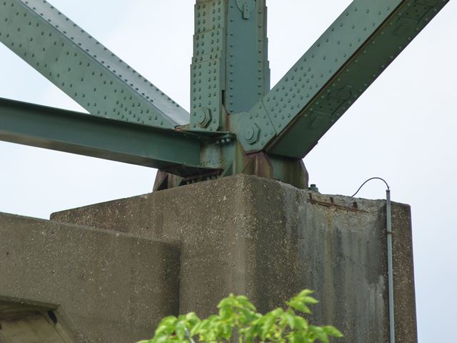
Approach span bearings.
![]()
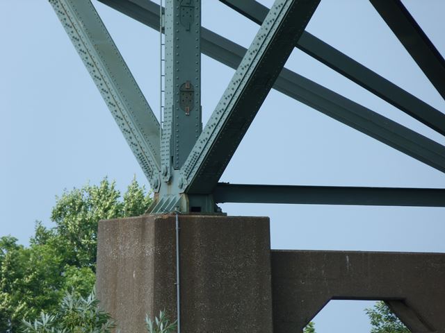
Channel span pier.
![]()
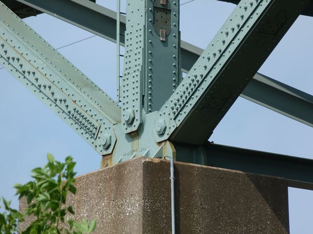
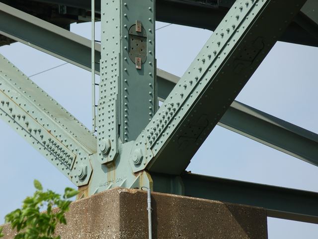
Channel span bearing.
![]()
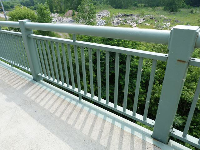
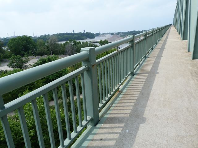
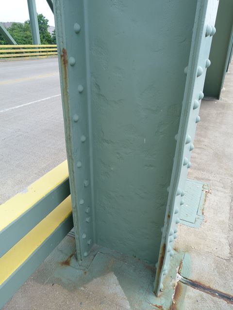
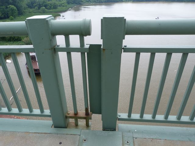
Railing.
![]()
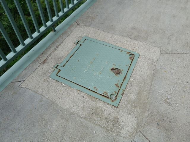
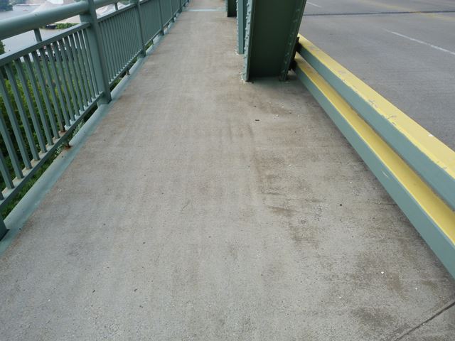
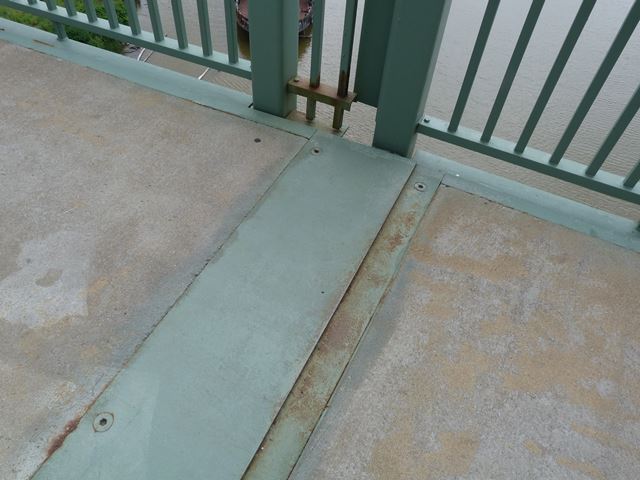
Sidewalk deck.
![]()
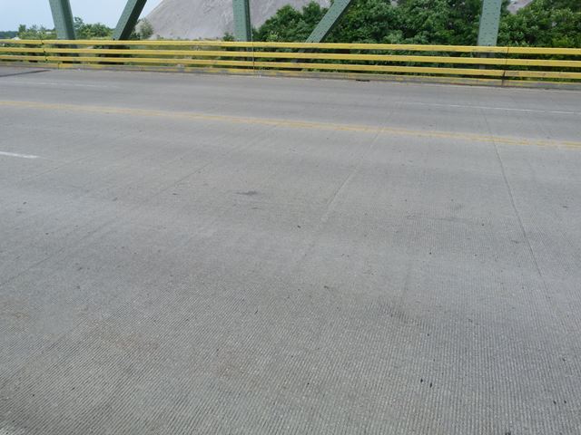
Roadway deck.
![]()
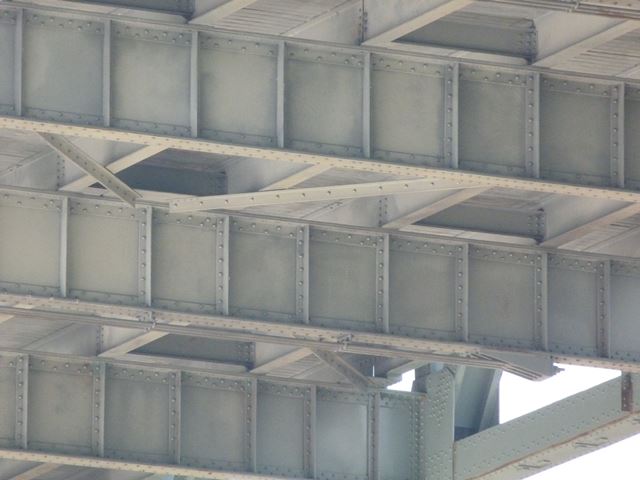
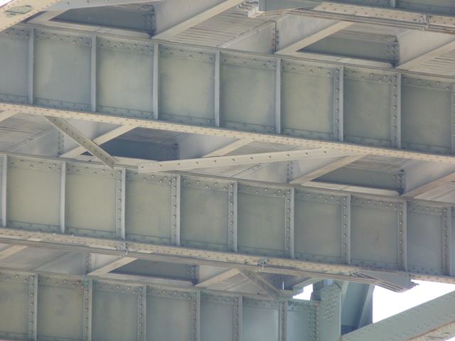
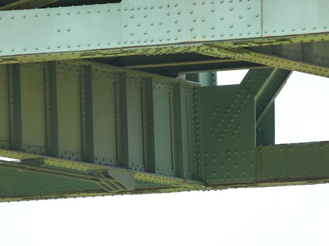
Floor beams.
![]()
![]()

![]()