We Recommend:
Bach Steel - Experts at historic truss bridge restoration.
BridgeHunter.com Phase 1 is released to the public! - Visit Now
IN-26 Bridge
State Highway Bridge 3346

Primary Photographer(s): Nathan Holth
Bridge Documented: February 19, 2017
Rural: Tippecanoe County, Indiana: United States
Metal 9 Panel Rivet-Connected Parker Through Truss, Fixed and Approach Spans: Pre-Stressed Concrete Stringer (Multi-Beam), Fixed
1941 By Builder/Contractor: R. McCalman, Inc. of Danville, Illinois and Engineer/Design: Indiana State Highway Commission
1977
200.0 Feet (61 Meters)
321.5 Feet (98 Meters)
26 Feet (7.92 Meters)
1 Main Span(s) and 3 Approach Span(s)
6690

View Information About HSR Ratings
Bridge Documentation
This bridge no longer exists!
Bridge Status: Demolished and replaced.View Archived National Bridge Inventory Report - Has Additional Details and Evaluation
View Historic Drawings and Plans For This Bridge
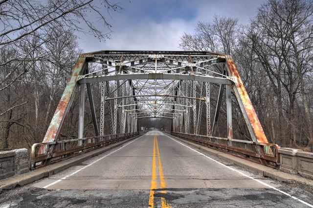
This is a classic example of an Indiana state highway through truss with arched portal bracing. The truss bridge replaced a previous bridge at this location which was a three span concrete arch bridge.
Information and Findings From DHPA Historic Bridge SurveyStatement of Significance R. McCalman, Inc. of Danville, Illinois, secured a $69,913.41 contract in April 1941 to build this four-span structure of state design upon concrete piers and abutments. The plan called for three reinforced concrete T-beam approach spans (1@30'; 2@40') to the West of a long Parker through-truss span over the river. The new structure was probably completed either near the end of 1941 or in early 1942. The ISHC had developed standard plan #1521 for a 200-ft. span with a 26-ft. roadway sandwiched between a pair of 2-ft. walks. Truss depth varied from 24 ft. at the portal to 39 ft. at midspan. Each truss carried nine panels, the outer two on each end at 20 ft. 7.5 in. and the inner five at 23 ft. 6 in. Every top chord member is differently sloped; only the central panel's one is parallel with the lower chord; and all were fabricated from a pair of 15-in. channels (@45# for the endposts, third, fourth, and fifth panels, and @40# for the second). For the lower chord, a pair of 15-in. channels riveted together with battens grow in weight from the outer panels (@40#) to the inner-most one (@55#). The state used rolled I-beams in a few web members. The verticals or posts consist of two forms and weights: the hip vertical is a 10-in. I-beam (@33#); the others are made from a pair of laced 10-in. channels (@15.3#). To protect the quite-tall trusses against wind and vehicle-induced stress, substantial latticed struts and heavy upper sway framing buttress the verticals above 15 ft. of roadway clearance. The portals used latticed sections, too. While a 10-in. I-beam (@41#) provided the second-panel diagonal, the third used a pair of laced 10-in. channels (@20#), the fourth a pair of 12-in. channels (@23.7#), and the fifth a 10-in. I-beam (@21#). Only the central panel was countered. The ISHC prescribed 30-in. I floor-beams increasing in weight toward midspan (@172#>200#) riveted to the verticals above the lower chord. Eight rows of rolled I-beam stringers attached to the floor-beams' sides varied in depth and weight by placement. The 20-ft. panels used 16-in. Is at 36 lbs. for the outside and 18-in. ones at 55 lbs. for the central ones. The 23-ft. 6-in. panels relied on 16-in. outer Is at 37 lbs and 21-in. Is at 29 lbs for the inner ones. Together, the floor-beams and the stringers carry the concrete deck. Angles supply each lower sway-bracing member. Tube-channel-and-post rails lined the inner sides of the trusses, and coped concrete approach rails with bush-hammered panels funneled traffic into the spans. In 1977, the state replaced the three T-beam spans with continuous prestressed concrete I-beam ones. This bridge illustrates the state's longest standard trussed span. The trusses retain their original members, including the metal guardrails. When the concrete T-beam spans were replaced, so were a few of the truss-span's stringers and concrete deck. The concrete approach rails were also removed to the West but remain on the East. Other Information References Indiana State Highway Commission, Structure #26-D-3346; Contract #2143; Superstructure Standard #1521. Bridge Considered Historic By Survey: Yes |
![]()
Photo Galleries and Videos: IN-26 Bridge
Bridge Photo-Documentation
Original / Full Size PhotosA collection of overview and detail photos. This gallery offers photos in the highest available resolution and file size in a touch-friendly popup viewer.
Alternatively, Browse Without Using Viewer
![]()
Bridge Photo-Documentation
Mobile Optimized PhotosA collection of overview and detail photos. This gallery features data-friendly, fast-loading photos in a touch-friendly popup viewer.
Alternatively, Browse Without Using Viewer
![]()
Maps and Links: IN-26 Bridge
This historic bridge has been demolished. This map is shown for reference purposes only.
Coordinates (Latitude, Longitude):
Search For Additional Bridge Listings:
Bridgehunter.com: View listed bridges within 0.5 miles (0.8 kilometers) of this bridge.
Bridgehunter.com: View listed bridges within 10 miles (16 kilometers) of this bridge.
Additional Maps:
Google Streetview (If Available)
GeoHack (Additional Links and Coordinates)
Apple Maps (Via DuckDuckGo Search)
Apple Maps (Apple devices only)
Android: Open Location In Your Map or GPS App
Flickr Gallery (Find Nearby Photos)
Wikimedia Commons (Find Nearby Photos)
Directions Via Sygic For Android
Directions Via Sygic For iOS and Android Dolphin Browser
USGS National Map (United States Only)
Historical USGS Topo Maps (United States Only)
Historic Aerials (United States Only)
CalTopo Maps (United States Only)

